
Related Manuals for DIG RBC MVA


Summary of Contents for DIG RBC MVA
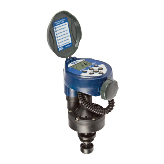
- Page 1 Battery Powered Actuator with Watering Timer RBC MVA I N S T R U C T I O N M A N U A L...
-
Page 2: Table Of Contents
6.1 Changing acuator adapters …………………………………………… 4 The RBC MVA Timer employs the latest irrigation programming features to allow for complete control of any irrigation system. The RBC MVA is a single station battery 6.2 Manual valve actuator installation …………………………………… 6 operated timer with a factory pre-assembled actuator to convert a 3/4 in. -
Page 3: Lcd Display And Controls
4. LCD DISPLAY AND CONTROLS Control Buttons Select programming mode Turn program(s) ON/OFF Battery replacement Start/stop a manual cycle Move left/right to select a value Raise/lower the selected value 5. INSTALLING THE BATTERIES 1. Open the battery compartment cap by LCD Display turning it counter-clockwise. -
Page 4: Changing Acuator Adapters
5. Install the 1 in. threaded adapter by pushing it onto the actuator The RBC MVA timer is factory set to fit a 3/4 in. brass manual anti-siphon valve. stem and making sure the notch To install the controller with actuator on a 1 in. manual anti-siphon valve, the 3/4 on the adapter lines up with the in. -
Page 5: Manual Valve Actuator Installation
6.2 MANUAL VALVE ACTUATOR INSTALLATION 5. Turn actuator flow control knob clockwise until it stops (Figure D). Rated operating pressure: 20 to 125 PSI 6. Turn on main water supply. Recommended operating pressure: 20 to 80 PSI 7. Activate the solenoid through the timer manual button, a click will be heard indicating the valve is open (The manual symbol will appear on the display). -
Page 6: Programming
7. PROGRAMMING The RBC MVA timer can be programmed to operate on any day of the week, odd days or even days. In cyclical mode the RBC can also operate from every 1 hour up to every 12 hours or from once a day up to every 30 days. The RBC has four start times per day and durations from 1 minute up to 5 hours and 59 minutes. -
Page 7: Setting Watering Day Schedules
9. SETTING WATERING DAY SCHEDULES Option 1 – Setting Specific Days of the Week: This setting determines which days the RBC MVA timer will operate. Choose either watering on specific days of the week, EVEN/ODD days or cyclical from daily up to once every 30 days. - Page 8 Option 4 – Setting every X days: Example: setting the timer to water every 10 days: 1. Press the button until the icon and the days of the week appear. 2. Press to skip all the days of the week (underscore must be 5.
-
Page 9: Setting Watering Start Times
OFF (or the first start time programmed) begins flashing. This setting determines the length of time the RBC MVA smart timer will allow the 3. To set the desired first start time hour (note AM and PM designations), press valve to remain open (duration is from 1 minute up to 5 hours and 59 minutes). -
Page 10: Setting Rain Delay - Optional Feature
12. SETTING RAIN DELAY – OPTIONAL FEATURE 2. Press the button, and 0:00 (or the last run time programmed) appears with hours flashing. The Rain Delay setting is used to temporarily suspend all irrigation for a defined number of days. For example, during rainy weather regularly scheduled programs 3. -
Page 11: Manual Watering
Note: OFF appears in between numeric value of 99 and 1. To activate a manual watering without the use of the timer – turn the solenoid a 1/4 turn counterclockwise. To stop, tighten the solenoid clockwise by hand Press the button to review the program or to exit. -
Page 12: Changing The Batteries
CAUSE: AM/PM not set correctly in current time mode The RBC MVA timer is designed to maintain the current time settings for up to 60 SOLUTION: Check current time, change AM/PM if necessary seconds with the batteries removed. -
Page 13: Warranty
Repair of damaged units not otherwise within warranty SOLUTION: Verify that sensor icon appears on display when pin is pushed may be refused or done at a reasonable cost or charge at the option of DIG CORPORATION. down & check all wire splices... -
Page 14: Technical Assistance
Should you encounter any problem(s) with this product or if you do not understand its many features, please refer to this operating manual first. If further assistance is required We at DIG Corporation understand that most dealers do not carry spare parts. For your DIG offers the following customer support: convenience, if you need one of these parts, please order online at www.digcorp.com. - Page 15 26-219 REV D 072116 1210 Activity Drive Printed in the USA Vista, CA 92081-8510, USA DIG is a Registered Service Mark of DIG Corp.
Need help?
Do you have a question about the RBC MVA and is the answer not in the manual?
Questions and answers