
Related Manuals for DIG LEIT 4000 Series


Summary of Contents for DIG LEIT 4000 Series
- Page 1 LEIT 4000 ® Ambient Light Powered Irrigation Controllers Instruction Manual I N S T R U C T I O N M A N U A L...
-
Page 2: Table Of Contents
TABLE OF CONTENTS A. Introduction ………………………………………………………………………… 1 B. About the LEIT 4000 Controller ……………………………………………………… 1 C. Technical Assistance ………………………………………………………………… 1 D. Copyright and Compliance …………………………………………………………… 1 E. Features …………………………………………………………………………… 1 1. System …………………………………………………………………………………… 2 1.1 Models available …………………………………………………………………… 2 1.2 Parts identification ………………………………………………………………… 2 1.3 USB updater ………………………………………………………………………... -
Page 3: Introduction
DIG LEIT irrigation controllers are available in two other models: LEIT X (without radio) or LEIT XRC (with radio control capability). -
Page 4: System
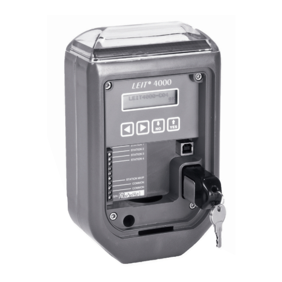
If you have purchased a LEIT 4008, you have the option to configure station 8 as a master valve when you install a master valve on your system. All LEIT 4000 series controllers are fitted with a wiring connector strip that has a maximum of 8 connector ports for hot wires (stations) and 2 connector ports for common wires. -
Page 5: Required System Components
Step 2 After the file has completed downloading, unzip it by double clicking on file. Step 3 Next plug the USB type B into the LEIT 4000 and the USB type A into your computer. If running Windows 7, please skip to step 5. Step 4 For computers running Windows Vista, XP or 2000, the computer auto-detects that a device has been connected and will ask you to install the proper drivers in order to establish a connection with the LEIT 4000 controller. -
Page 6: Tools And Supply Requirements
1.5 Tools and Supply Requirement 1. Battery: 9-volt alkaline battery for the LEIT Key 2. Standard wire stripper 3. Flathead screwdriver (9/64” or smaller) 4. Concrete: approximately three 60 lb (27 kg) bags 5. Conventional waterproof wire connectors 2. INSTALLATION Select the optimum location for the LEIT 4000 controller. -
Page 7: Wire Installation And Distance
VALVE FOR LEIT CONTROLLER ASSEMBLY VALVE FOR LEIT CONTROLLER ASSEMBLY DRY SPLICE CONNECTORS 18” VALVE BOX WITH COVER FINISH GRADE TOP DIG REMOTE CONTROL VALVE WITH FLOW CONTROL AND LEIT DC SOLENOID MODEL: 160HE-150 1-1/2” MODEL: 160HE-200 2” PVC SCH 40 MALE ADAPTER... -
Page 8: Sensor Installation
2. Run the field wires along their respective trenches from the valve Figure B1 box up to the bottom end of the mounting column. Make sure not to exceed the maximum recommended wire distance (see chart for maximum wire distance above). Push the wires up through the column until at least 12”... -
Page 9: Compatible Sensors
3.3 Sensors compatible with LEIT controllers Rain sensors are the HUNTER MINI-CLIK and the RAIN BIRD RSD. ® OPTION 1 Sensor connected to controller using SKIT adapter OPTION 2 Sensor connected to a valve using SKIT adapter Figure B Moisture sensors are the IRROMETER, and WEM-B (battery). Freeze sensor is the HUNTER FREEZE-CLIK or RAINCLIK™... - Page 10 ELECTRICAL EQUIPMENT RELAY INTERFACE CONNECTION LEGEND 4. RED WIRE TO THE MV/PUMP TERMINAL OR ANY STATION TERMINAL 1. FINISH GRADE 5. WHITE WIRE TO THE COMMON TERMINAL 2. 6” ROUND VALVE BOX 6. DRY SPLICE CONNECTORS (4) 3. RKIT ADAPTER PART NO. 8810-S. USE WITH EACH SENSOR 7.
- Page 11 SENSOR INSTALLATION LEGEND “MINI CLIK” RAIN SENSOR. DIG PLASTIC PIPE CAP – 1” CAP PART NO. 23-001 OR 1.5” CAP PART NO. 23-153 WITH HOLE FOR WIRES. DRILL TWO 3/16 HOLES IN PIPE FOR SENSOR BRACKET. (2) #8-32 MACHINE SCREWS WITH WASHER, LOCK WASHER AND NUT.
-
Page 12: Programming
LEIT CONTR LEGEND DRY SPLICE WATERPROOF CONNECTORS 18” VALVE BOX WITH COVER FINISH GRADE TOP DIG REMOTE CONTROL VALVE WITH FLOW CONTROL AND LEIT DC SOLENOID MODEL: 160HE-150 1-1/2” MODEL: 160HE-200 2” PVC SCH 40 MALE ADAPTER PVC MAIN LINE BRICK SUPPORT AT EACH CORNER PEA GRAVEL SUMP MINIMUM 3”... -
Page 13: Manual Run
INSERT LEIT KEY INTO THE SOCKET IN THE UPPER LEFT CORNER OF THE CONTROLLER. The above screens appear while the controller is charging. NOTE: If the controller is being programmed for the first time under a low light level it may take up to 5 minutes to charge the controller using the LEIT Key. -
Page 14: Rain Stop/Restart
and select temp by pressing , then press Run Prog. l None l Stored l Temp button again and underscore OK, press and the next screen will appear. Press to underscore the hour or minute digits, then Valve #1___0:01 press to adjust the runtime. -
Page 15: Monthly Budget
press to underscore OK. Press to continue. Stop for 00 Days To implement a Rain Stop press and underscore 0 days. Press and enter the number of days needed to suspend irrigation (from 1-99 days). Press to underscore OK. Press to continue. -
Page 16: Setup Schedule
3. Press to review valve number current month uses. Sensor is Reports how much time was logged on each of your valves Unused. during the current month. 4. Press to review the individual log for each valve. Press Valve #_____ Use This after the last valve report to review the previous month Month: 0:37... - Page 17 Even- every even numbered day Every l Even Odd- every odd numbered day l MTWTFSS l Odd MTWTFSS- lets you select specific day(s) of the week to irrigate. Underscore the preferred option by using , then press again. If you select MTWTFSS, you’ll .
-
Page 18: Setup System
Once you have completed program 1, you’ll find yourself back in the Setup Schedule display. Press you want to repeat the setup procedure, to enter another program or press to make corrections to the existing program OR press the to continue to the next step. 5.6 SETUP SYSTEM This part of the menu enables you to set the correct time and date, activate or de-activate programs, change passwords, etc. - Page 19 NOTE: Scheduled programs will not run unless you activated the appropriate program number in this screen. Valve #1 Options: This setting has two options for each valve. n MV/P 4 Budget Option one, MV/P: if checked, the valve # will operate with an installed master valve or pump.
- Page 20 At this screen, you can set up any or all of the installed valves Sensor 4 1 n 2 to be switched off when the sensor is triggered. Checkmark Governs: n 3 the boxes next to the station numbers that you wish to be governed by the sensor by using and underscore the appropriate box, by pressing...
-
Page 21: Troubleshooting
6. TROUBLESHOOTING The LEIT irrigation control system is a series of connected components consisting of an ambient light powered controller, LEIT Key, LEMA actuators, hydraulic control valves, and field wires/splices. It is best to troubleshoot this DC system (like an AC system) by a process of elimination; the goal being to determine which component(s) has failed. -
Page 22: Hydraulic Valves
6. Sometimes it may be prudent to run temporary wires above grade to the valve to verify a problem with the wire. 7. Wire problems are not the responsibility of DIG Corp. 8. If the same color hot wires are run to all valves, the wires should be identified and tagged with... -
Page 23: Warranty
(4) years, from the date of original purchase. If any apparent defect arises under normal use and service in the LEIT product within the warranty period, DIG at its sole discretion, shall have the option to repair or replace part or all of the original product free of charge after return of such product at user expense, authorized in writing by DIG Corp. -
Page 24: Leit Control Programming Quick Reference Chart
8. LEIT CONTROL PROGRAMMING QUICK REFERENCE CHART... -
Page 26: Usb Updater
9. LEIT 4000 USB UPDATER The LEIT 4000 is now supplied with a convenient USB port in order for your controller to be kept up to date with new software versions. Before attempting to update to the most recent software version on your LEIT controller, first check to see if your controller has the current software installed. - Page 27 Step 7 Follow all instructions on screen to complete the update process of your LEIT 4000 controller (see Figure A). After the update process is complete, disconnect the USB cable (see Figure B). Note: If the LEIT 4000 is installed, use a laptop to update the controller in the field. FIGURE A FIGURE B USB TYPE B...
- Page 28 1210 Activity Drive 26-400 REVA 050216 Vista, CA 92081-8510, USA Printed in the USA...
Need help?
Do you have a question about the LEIT 4000 Series and is the answer not in the manual?
Questions and answers