Table of Contents
Advertisement
Quick Links
PROPER USE GUIDELINES
Cumulative Trauma Disorders can result from the prolonged use of manually powered hand tools. Hand tools are intended for occasional use and low volume
applications. A wide selection of powered application equipment for extended-use, production operations is available.
Color Code for PIDG* and
PLASTI-GRIP* Products
Wire Size Range
Stamped Here
Insulation Crimp Adjustment
Pins in No. 3 Position
1. INTRODUCTION
This instruction sheet covers the Hand Crimping Tools
listed in Figure 1, which are used to crimp the
terminal types listed in Figure 2.
Dimensions on this sheet are in millimeters
NOTE
[with inch-equivalent dimensions in brackets].
Figures and illustrations are for identification only
i
and are not drawn to scale.
Reasons for reissue are provided in Section 9,
REVISION SUMMARY.
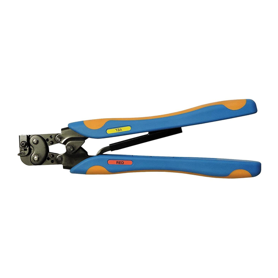
2. DESCRIPTION
(Figure 1)
The handles and label (if applicable) of the crimping
tools are color–coded to match the color coding of the
E
2007 Tyco Electronics Corporation, Harrisburg, PA
All International Rights Reserved
TE logo and Tyco Electronics are trademarks.
*Trademark. Other products, logos, and company names used are the property of their respective owners.
Hand Crimping Tools
CERTI-CRIMP* Hand
Crimping Tool Ratchet
Control
Color Code for
Sealed Splices
Figure 1
connectors to be applied, as listed in Figure 3. The
crimping tools may show more than one color code.
Check Figure 3 to be sure that the correct tool/
connector combination is being used.
For example, tool 47386 can be used to apply PIDG
terminals and splices with a yellow color code, as well
as spare wire caps with a red color code.
Figure 3 lists the number of dots (or rib) that appear
embossed on a crimped item when the connector is
crimped in the correct tooling.
The CERTI–CRIMP hand crimping tool ratchet control
ensures full crimping of terminals and splices. Once
engaged, the ratchet will not release until the tool
handles have been FULLY closed.
TOOLING ASSISTANCE CENTER 1-800-722-1111
PRODUCT INFORMATION 1-800-522-6752
Instruction Sheet
408-1559
19 JUN 07
HAND CRIMPING TOOL PART NUMBERS
46121
47387
47304
47907-1
47386
48518-2
47386-5
This controlled document is subject to change.
For latest revision and Regional Customer Service,
www.tycoelectronics.com
visit our website at
Rev P
69151-1
69454
169485
1
of 10
LOC B
Advertisement
Table of Contents

Related Manuals for Tyco Electronics 46121


Summary of Contents for Tyco Electronics 46121
- Page 1 For latest revision and Regional Customer Service, All International Rights Reserved www.tycoelectronics.com visit our website at TE logo and Tyco Electronics are trademarks. LOC B *Trademark. Other products, logos, and company names used are the property of their respective owners.
-
Page 2: Connector Type
4. Close the tool handles until the terminal or splice is held firmly in place. Do NOT deform the terminal 9. Refer to Section 4 and Figure 7 for spare wire or splice wire barrel. cap crimp inspection procedure. of 10 Tyco Electronics Corporation... - Page 3 1.04-2.62 [16-14] BLUE RESISTANT 0.41-1.65 [20-16 HD] BLUE AND TERMINALS GREEN (RADIATION 16-14 GREEN 47387 AND SPLICES 20-16HD RESISTANT NATURAL COLOR TRANSLUCENT DOTS W/BLUE STRIPE) TIGHT INSULATION SUPPORT FOR WIRES WITH THIN WALL INSULATION Figure 3 (cont’d) of 10 Tyco Electronics Corporation...
- Page 4 Butts Against Tool Locator “C” “B” “C” “B” (Note: Wire Butts Against Wire Stop B" Equals FASTON Receptacle Wire Wire Barrel Stop) C" Equals Insulation PIDG FASTON Receptacle PLASTI-GRIP Terminal Barrel Figure 4 4 of 10 Rev P Tyco Electronics Corporation...
-
Page 5: Crimp Inspection
The insulation crimping section of the hand tool has CAUTION Make sure that both insulation crimp adjustment three positions: 1 (tight), 2 (medium), and 3 (loose). pins are in the same position. To adjust the section: of 10 Tyco Electronics Corporation... -
Page 6: Maintenance/Inspection
3. Make certain that all pins, pivot points, and shipping container, file a claim with the carrier, and bearing surfaces are protected with a THIN coat notify Tyco Electronics immediately. of any good SAE 20 motor oil. Do NOT oil excessively. -
Page 7: Replacement And Repair
This inspection requires the use of plug gages the following sequence: conforming to the dimensions listed in Figures 8 and 9. Tyco Electronics does not manufacture or A. Visual Inspection market these gages. 1. Remove all lubrication and accumulated film by... - Page 8 Hold tool must be repaired. Refer to Section 8, the tool in this position, maintaining just enough REPLACEMENT AND REPAIR. pressure to keep the dies closed. of 10 Tyco Electronics Corporation...
-
Page 9: Customer Service
Figure 11 should be replaced by S Updated document to corporate requirements Tyco Electronics to ensure quality and reliability of the S Added part number 47386–5 to tables in tool. Order replacement parts through your Tyco Electronics Representative, or call 1–800–526–5142,... - Page 10 21045-6 PIN, Retaining 2-23620-9 2-23620-9 2-23620-9 2-23620-9 SCREW 9-305927-1 3-306105-9 9-305927-1 9-305927-1 SUPPORT STOP HOUSING LOCATOR 302994 302994 302994 302994-1 SPRING 301201 301201 301201 2-304668-6 LOCATOR 575960-4 125644-7 302993 4-304052-6 Figure 11 10 of 10 Rev P Tyco Electronics Corporation...
Need help?
Do you have a question about the 46121 and is the answer not in the manual?
Questions and answers