
Related Manuals for Advantech PCI-1220U


Summary of Contents for Advantech PCI-1220U
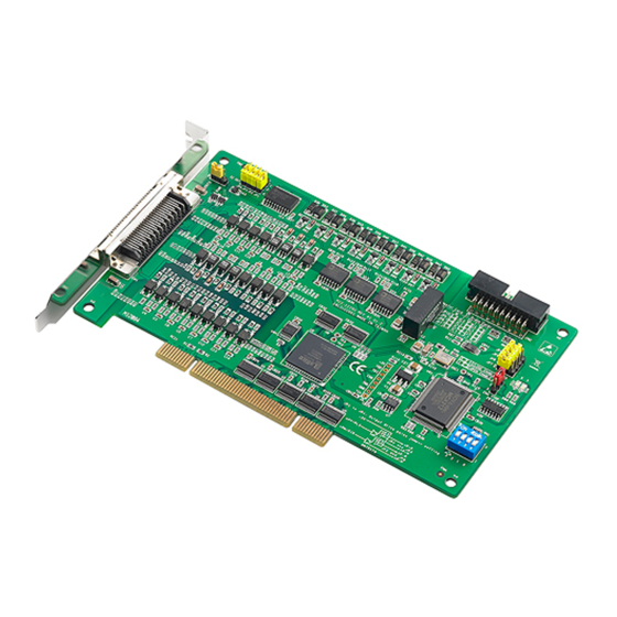
- Page 1 PCI-1220U 2-axis Universal PCI Stepping/ Pulse-type Servo Motor Control Card User Manual...
- Page 2 Acknowledgments PC-LabCard is a trademark of Advantech Co., Ltd. IBM and PC are trademarks of International Business Machines Corporation. MS-DOS, ®...
- Page 3 Product Warranty (2 years) Advantech warrants to you, the original purchaser, that each of its prod- ucts will be free from defects in materials and workmanship for two years from the date of purchase. This warranty does not apply to any products which have been repaired or...
- Page 4 Step 1. Visit the Advantech web site at www.advantech.com/support where you can find the latest information about the product. Step 2. Contact your distributor, sales representative, or Advantech's cus- tomer service center for technical support if you need additional assistance. Please have the following information ready before...
-
Page 5: Table Of Contents
Contents Chapter 1 Introduction ............. 2 Features ................2 Applications ..............5 Installation Guide .............. 5 Accessories................ 6 Chapter 2 Installation ............8 Unpacking ................. 8 Driver Installation ............. 9 Installation Instructions ............. 9 Chapter 3 Signal Connections ........12 I/O Connector Pin Assignments........ - Page 6 Appendix C Wiring with Third-Party Motor Drivers ..46 Figure C.1:Mitsubishi MR-J2S Series Motor Driver ... 46 Figure C.2:Oriental LIMO EZMC Motor Driver ..47 Figure C.3:Panasonic MINAS-A Series Motor Driver 48 Figure C.4:Yaskawa SGDM Series Motor Driver ..49 PCI-1220U User Manual...
- Page 7 Introduction This chapter introduces PCI-1220U and lists features and specifications.
-
Page 8: Chapter 1 Introduction
Moreover, through a free bundled motion utility, you can complete con- figuration and diagnosis easily. 1.1 Features PCI-1220U provides users with the most requested motor control func- tions as seen below: • Independent 2-axis motion control • Support hand wheel and jog function •... - Page 9 The Advantech PCI-1220U offers the following main features: Individual Control for 2 Axes Each of the axes has identical capabilities, and is controlled by the same method of operation with constant speed, trapezoidal or S-curve driving. Programmable T/S-curve Acceleration and Deceleration Each of four axes can be preset individually with S-curve or trapezoidal acceleration/deceleration rates.
- Page 10 Interrupt signals can be generated when: (1) the start/finish of a constant speed drive during the trapezoidal driving, (2) the end of driving, and (3) the compare result higher/lower the border-lines of the position counter. An interrupt signal can be also generated during the interpolation driving. PCI-1220U User Manual...
-
Page 11: Applications
• Semiconductor pick and place and testing equipment • Other stepping/pulse-type servo motor applications 1.3 Installation Guide Before you install your PCI-1220U card, please make sure you have the following necessary components: • PCI-1220U Motion Card • PCI-1220U Startup Manual •... -
Page 12: Accessories
1.4 Accessories Advantech offers a complete set of accessory products to support the PCI-1220U card. These accessories include: Wiring Cable • PCL-10152 The PCL-10152 shielded cable is specially designed for PCI-1220U card to provide higher resistance to noise. To achieve a better signal quality, the signal wires are twisted in such away as to form a “twisted-pair cable”,... - Page 13 12202 Installation This chapter gives users a package item checklist, proper instructions about unpacking and step-by-step procedures for both driver and card installation.
-
Page 14: Chapter 2 Installation
Chapter 2 Installation 2.1 Unpacking After receiving your PCI-1220U package, please inspect its contents first. The package should contain the following items: • PCI-1220U Card • Companion CD-ROM (DLL driver included) • User Manual The PCI-1220U card harbors certain electronic components vulnerable to electrostatic discharge (ESD). -
Page 15: Driver Installation
Save the screw to secure the interface card retaining bracket. 5. Carefully grasp the upper edge of the PCI-1220U. Align the hole in the retaining bracket with the hole on the expansion slot and align the gold striped edge connector with the expansion slot socket. - Page 16 PCI-1220U User Manual...
- Page 17 Signal Connections This chapter provides useful informa- tion about how to connect input and output signals to the PCI-1220U via the I/O connector.
-
Page 18: Chapter 3 Signal Connections
BoardID setting is useful for identifying each card’s device number. We set the BoardID switch of PCI-1220U to 0 at the factory. If you need to adjust it to another number, set SW1 by referring to Table 3.3. - Page 19 Figure 3.1: I/O Connector Pin Assignments Chapter 3...
- Page 20 Jog at the - Direction of X axis YEXOP+ Input Jog at the + Direction of Y axis YEXOP- Input Jog at the - Direction of Y axis Ground XOUT0 Output General Output at X axis (CMP+) PCI-1220U User Manual...
- Page 21 Table 3.1: I/O Connector Signal Description (continued) XOUT1 Output General Output at X axis (CMP-) XOUT2 Output General Output at X axis (Server XOUT3 Output General Output at X axis XP+P Output Output pulse CW/Pulse+ of X- axis XP+N Output Output pulse CW/ Pulse- of X- axis XP-P...
- Page 22 ID3: the most significant bit (MSB) of Board ID Table 3.3: BoardID setting Board ID setting (SW1) Board ID (Dec.) Switch Position = Off = On * = default PCI-1220U User Manual...
-
Page 23: Output Pulse Definition
3.3 Output Pulse Definition The output pulse command of PCI-1220U is from MCX312 chip. The pulse command has two types. One is in Up/Down mode and another is in Pulse/Direction mode. While nP+P is differential from nP+N and nP-P is differential from nP-N. After system reset, the nP+P and nP-P is low level, and this invert output (nP+N, nP-N) is high level, and the de-fault setting of pulse output mode is Up/Down. - Page 24 Figure 3.4: Photo Coupler Input Interface Figure 3.5: Line Driver Input Interface PCI-1220U User Manual...
-
Page 25: General Purposed Output
3.4 General Purposed Output The general purposed output nOUT3/DSND, nOUT2/ASND, nOUT1/ CMPM, and nOUT0/CMPP are from MCX312, and each output signal is OFF status after system reset. Figure 3.6: General Purpose Output General purposed output signals used in motor drives can clear error counter, alarm reset, stimulus off, etc., or select acceleration/deceleration for driving, position counter, and the status of comparison register as your output during driving. - Page 26 3-8 is an example of photo sensor used in the case of over traveling limit switch input. When writing D3 bit of register2 (XWR2) into 0 to set the limit switch is low active in X-axis, the following figure can work normally. Figure 3.8: Photo Sensor in the Limit Input Signal PCI-1220U User Manual...
-
Page 27: Deceleration/Instantaneous Stop Switch Input
3.6 Deceleration/Instantaneous Stop Switch Input Note: When the axis/axes is/are about to stop (in the decelera- tion stage), the axis/axes will not stop totally but keep moving at a very low speed if you use S-curve accelera- tion/deceleration to control speed under the “Point to Point”... -
Page 28: General Purposed Input For Servo Drives
When servo drives have an abnormal condition, they active this signal to note PCI-1220U to stop output pulses. When enable the nALARM func- tion of PCI-1220U, the D14 bit of RR2 will set to 1 after nALARM active. If PCI-1220U is driving pulses output, the output pulses will stop immediately when nALARM active. -
Page 29: Encoder Input
Figure 3.11: Circuit Diagram of Encoder Feedback From the circuit diagram above, PCI-1220U uses high speed photo cou- pler for isolation. The encoder output can be differential mode or open- collector mode. When n***P is high and n***N is low, the real feedback signal (n***) to MCX312 is low. - Page 30 The following diagram is an example of the connection for encoder with differential-output linear driver. Figure 3.12: Differential-output Line Driver The following figure is an example of connection for the encoder with open-collector output. Figure 3.13: Open Collector Output Encoder PCI-1220U User Manual...
-
Page 31: External Pulse Control Input
(nEXOP+, nEXOP-). There are two output pulse mode for the external control pin. One is fixed pulse out- put mode, and the other is continuous output mode. In PCI-1220U, it pro- vides Jog and Hand wheel functions that allow you driving motors through external Hand wheel or Jog equipment. -
Page 32: Emergency Stop Input (Emg)
3.11 External Power Input (VEX) External power is necessary for all input signals of each axis. Please apply DC12~24V voltage as your need. Current consumption of each point for input signal is DC12V = 3.3 mA, DC24V = 7 mA. PCI-1220U User Manual... -
Page 33: Interrupt Setting
When the interrupt occurs from MCX312, the interrupt signal of MCX312 will be changed from high to low. Because the PCI bus inter- rupt is high level sensitive, the PCI-1220U inverse the signal and latch the signal to adapt the PCI bus INTA. The Fig- 3.17 shows the interrupt structure of the PCI-1220U. -
Page 34: Connection Examples For Motor Drivers
Which will be controlled by setting D8, D9 of WR3 in MCX312. And, read the RR4,5 to know the status of XEZ+/-. The following figure is an example of PCI-1220U connected to UPK step drive manufactured by ORIENTAL company. PCI-1220U User Manual... - Page 35 Figure 3.19: Connecting to UPK Step Drive Note The differential pulse output of PCI-1220U is connected to CW/CCW input of UPK drive. XOUT0 can control UPK drive to hold by setting D8 of WR3. TIMING and Over HEAT signals can be read back by reading RR4,5.
-
Page 36: Connection To Servo Motor Drivers
3.13.2 Connection to Servo Motor Drivers The figure shown below is an example of PCI-1220U connected to MINAS X series AC servo motor drive. Figure 3.20: MINAS X Series AC Servo Motor Drive Note The servo drive must be set in pulse-control drive mode and the type of pulse input is CW/CCW mode. -
Page 37: Field Wiring Considerations
3.14 Field Wiring Considerations When you use the PCI-1220U to acquire data from outside, noises in the environment might significantly affect the accuracy of your measure- ments if due cautions are not taken. The following measures will be helpful to reduce possible interference running signal wires between sig- nal sources and the PCI-1220U. -
Page 38: I/O Signal Timing
• Output pulses (nP ± P, nP ± N) for drive control and general purpose output signals (nOUT0 ~ 3) for I/O control will be determined after 250 nsec from power on reset. • User can access PCI-1220U only after 500 nsec from power-on reset. 3.15.2 Individual Axis Driving Figure 3.22: Individual Axis Driving •... -
Page 39: Interpolation Driving
3.15.3 Interpolation Driving Figure 3.23: Timing Diagram of Interpolation Driving • After interpolation command is enable, the first pulse will be outputted in 775 nsec. • If using pulse/direction mode, direction signal (nP-P) is valid in ± 125 nsec of high-level pulse signal. 3.15.4 Input Pulse Timing Quadrature Pulse of Encoder Input Figure 3.24: Quadrature Pulse of Encoder Input... -
Page 40: Instantaneous Stop Timing
• When external deceleration signal is enabled during driving, up to 400 µ SEC + 2 pulses will be output, and then stopped. Deceleration/Stop Instruction Figure 3.29: Deceleration/Stop Instruction • When the Deceleration/Stop instruction is issued during driving, at most two pulses will be output, and then stopped. PCI-1220U User Manual... -
Page 41: Ttl Level Position Compare Output
3.16 TTL Level Position Compare Output This is a special design for the customers who can use the position com- pare output to synchronize with other vision devices. For PCI-1220U, the position compare output channels are nOUT0 and nOUT1, and it is open- collector type output. - Page 42 PCI-1220U User Manual...
- Page 43 Specifications...
-
Page 44: Appendix A Specifications
Pulse/Direction (1-pulse, 1-direc- Type tion type) or Up/Down (2-pulse type) Output Signal Differential line driving output / Modes Single-ended output Speed Curve T/S curve acceleration/deceleration Note *: “n” represents the axis (X, Y, Z or U) that is concerned PCI-1220U User Manual... -
Page 45: Digital Input/Output
A.2 Digital Input/Output Input Signals Over Traveling nLMT+, nLMT- Limit Switch Input* General Input nIN0~1 Signal* Input Signal for nALARM (servo alarm); nINPOS Servo Motor (position Drives* command completed) Emergency Stop EMG - one emergency stop input Max. Input 4 kHz Frequency Input Voltage Logic 0 21~24 V... -
Page 46: External Signals Driving
-2,147,438,648 ~ +2,147,438,647 Interrupt Interrupt Condition Position Counter => Functions (All conditions could be COMP- (Excluding enabled/disabled individually) Position Counter < Interpolation) COMP- Position Counter < COMP+ Position Counter => COMP+ BoardID 4-bit DIP switch, ID: 0~15 PCI-1220U User Manual... -
Page 47: General
A.6 General I/O Connector Type 50-pin SCSI-II female Dimensions 175 x 100 mm (6.9” x 3.9”) Power Consumption Typical. 300 mA @ 5 V Max. 600 mA @ 5 V External Power Voltage DC +12 ~ 24 V Temperature Operating 0 ~ 60° C (32 ~ 140° F) (refer to IEC 68-2-1,2) Storage -20 ~ 85°... - Page 48 PCI-1220U User Manual...
- Page 49 Block Diagram...
-
Page 50: Appendix B Block Diagram
Appendix B Block Diagram PCI-1220U User Manual... - Page 51 Wiring with Third-Party Motor Drivers...
-
Page 52: Appendix C Wiring With Third-Party Motor Drivers
Appendix C Wiring with Third-Party Motor Drivers Figure C.1: Mitsubishi MR-J2S Series Motor Driver PCI-1220U User Manual... - Page 53 Figure C.2: Oriental LIMO EZMC Motor Driver Chapter C...
- Page 54 Figure C.3: Panasonic MINAS-A Series Motor Driver PCI-1220U User Manual...
- Page 55 Figure C.4: Yaskawa SGDM Series Motor Driver Chapter C...
- Page 56 PCI-1220U User Manual...
Need help?
Do you have a question about the PCI-1220U and is the answer not in the manual?
Questions and answers