
Subscribe to Our Youtube Channel
Related Manuals for ADLINK Technology 10GbE BASE-T


Summary of Contents for ADLINK Technology 10GbE BASE-T
- Page 1 10GbE BASE-T Card User’s Manual COM Express Type 7 10GBASE-T Network Adapter Card Manual Rev.: Revision Date: July 7, 2017 Part Number: 50-1J091-1000 Leading EDGE COMPUTING...
- Page 2 Preface Copyright Copyright 2017 ADLINK Technology, Inc. This document contains proprietary information protected by copyright. All rights are reserved. No part of this manual may be reproduced by any mechanical, electronic, or other means in any form without prior written permission of the manufacturer.
-
Page 3: Table Of Contents
2.6. Functional Diagram.....................4 2.7. Mechanical Drawing ....................5 Pinouts and Signal Descriptions................7 3.1. Input Interface Definitions ...................7 Module Interfaces and Configuration ..............9 4.1. 10GbE BASE-T Card Layout ..................9 4.2. 10GbE Adapter Card Installation ................10 4.3. LED Indicators ......................11 Getting Service.........................12 Preface... -
Page 4: List Of Figures
List of Figures Figure 1: 10GbE BASE-T Card Functional Block Diagram ..............4 Figure 2: 10GbE BASE-T Card Mechanical Drawing................5 Figure 3: 10GbE BASE-T Card Layout ....................9 Figure 4: 10GbE Adapter Card Installed on Express-BASE7 with Type 7 COM Express Module ..10... -
Page 5: List Of Tables
10GbE BASE-T Card List of Tables Table 1: 10GbE BASE-T Card Pin Definitions ..................7 Table 2: LED Descriptions........................11 Preface... - Page 6 This page intentionally left blank. Preface...
-
Page 7: Introduction
It converts up to four 10GBASE-KR interfaces & related sideband signals to four 10GbE copper interfaces (10GBASE-T signals) through 10GbE copper PHY. The 10GbE BASE-T Card can only be used on products that are PICMG COM Express Type 7 (COM.0 Rev. 3.0) compliant. - Page 8 This page intentionally left blank. Introduction...
-
Page 9: Specifications
10GbE BASE-T Card 2. Specifications 2.1. Interface Input Up to four 10GBASE-KR & related sideband signals from COM Express Type7 module through 164-pin edge connector (PCIe x16 slot PCIEKR on Express-BASE7) Output Up to four 10G copper signals (10GBASE-T) 2.2. -
Page 10: Functional Diagram
2.6. Functional Diagram Figure 1: 10GbE BASE-T Card Functional Block Diagram Specifications... -
Page 11: Mechanical Drawing
44.80 11.92 4.85 All dimensions are shown in millimeters. Tolerances should be ± 0.25mm, unless otherwise noted. The tolerances of the holes (dimensions [0, 0] and [0, 96.95]) should be ± 0.10mm. Figure 2: 10GbE BASE-T Card Mechanical Drawing Specifications... - Page 12 This page intentionally left blank. Specifications...
-
Page 13: Pinouts And Signal Descriptions
3.1. Input Interface Definitions The 10GbE BASE-T Card is a Type 7 compliant 10GbE adapter card that receives 10GBASE-KR and sideband signals from the COM Express Type7 module and converts them 10GbE copper signals (10GBASE-T). Table 1: 10GbE BASE-T Card Pin Definitions... - Page 14 Row B Row A Name Name 10G_KR_TX1- 10G_PHY_MDIO_SDA1 10G_PHY_MDC_SCL1 10G_PHY_MDIC_SDA0 10G_PHY_MDC_SCL0 10G_KR_RX0+ 10G_KR_RX0- 10G_KR_TX0+ 10G_KR_TX0- 10G_PHY_CAP_23 10G_PHY_CAP_01 Note: Four 10GbE ports are supported by project basis. Pinouts and Signal Descriptions...
-
Page 15: Module Interfaces And Configuration
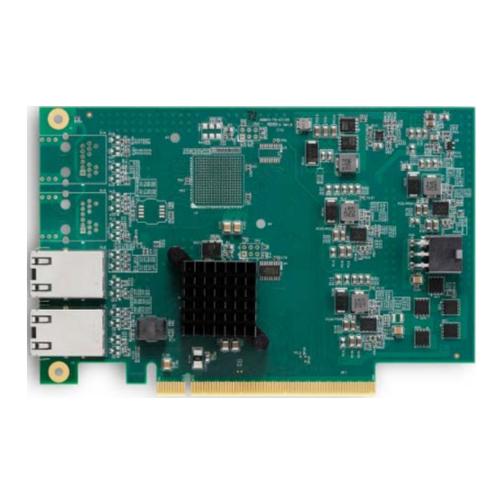
This chapter describes connectors and pinouts, LEDs and switches that are used on the 10GbE adapter card. 4.1. 10GbE BASE-T Card Layout Reserved Connector 10GbE Ports Heatsink for Ethernet Connector (PHY) Figure 3: 10GbE BASE-T Card Layout Note: See 4.3 LED Indicators for detailed 10GbE port status LED information. Module Interfaces and Configuration... -
Page 16: 10Gbe Adapter Card Installation
4.2. 10GbE Adapter Card Installation Below is an example of a 10GbE adapter card installed on the Express-BASE7 carrier board with a Type 7 COM Express Module (or illustration purposes only). COM Express Type 7 module Express-BASE7 10GbE adapter card PCIe x16 slot (PCIEKR) dedicated for 10GbE adapter card Figure 4: 10GbE Adapter Card Installed on Express-BASE7 with Type 7 COM Express Module Module Interfaces and Configuration... -
Page 17: Led Indicators
10GbE BASE-T Card 4.3. LED Indicators There are two status LEDs for each 10GBASE-T port (link and activity). Link (yellow) Port 3 Activity (green) Link (yellow) Port 2 Activity (green) Link (yellow) Port 1 Activity (green) Link (yellow) Port 0... -
Page 18: Getting Service
5215 Hellyer Avenue, #110, San Jose, CA 95138, USA Tel: +1-408-360-0200 Toll Free: +1-800-966-5200 (USA only) Fax: +1-408-360-0222 Email: info@adlinktech.com ADLINK Technology (China) Co., Ltd. Address: 300 Fang Chun Rd., Zhangjiang Hi-Tech Park, Pudong New Area Shanghai, 201203 China Tel: +86-21-5132-8988 Fax: +86-21-5132-3588 Email: market@adlinktech.com...
Need help?
Do you have a question about the 10GbE BASE-T and is the answer not in the manual?
Questions and answers