Table of Contents
Advertisement
Available languages
Available languages
Quick Links
ECOMONOBLOCCO WT60 3D
MANUALE DI INSTALLAZIONE, USO E MANUTENZIONE
Il presente manuale è parte integrante del prodotto.
Si raccomanda di leggere attentamente le istruzioni prima
dell'installazione, manutenzione o utilizzo del prodotto.
Istruzioni originali
INSTALLATION, USE AND MAINTENANCE MANUAL
This manual is an integral part of the product.
Read the instructions carefully before installing, servicing or
operating the product.
Translation of the original instructions
MANUEL D'INSTALLATION, D'UTILISATION ET DE MAINTENANCE
Le présent manuel fait partie intégrante du produit.
Il est conseillé de lire attentivement les consignes avant
l'installation, l'entretien ou l'utilisation du produit.
Traduction des instructions originales
Advertisement
Table of Contents

Subscribe to Our Youtube Channel
Related Manuals for Palazzetti WT60 3D N16


Summary of Contents for Palazzetti WT60 3D N16
- Page 1 ECOMONOBLOCCO WT60 3D MANUALE DI INSTALLAZIONE, USO E MANUTENZIONE Il presente manuale è parte integrante del prodotto. Si raccomanda di leggere attentamente le istruzioni prima dell’installazione, manutenzione o utilizzo del prodotto. Istruzioni originali INSTALLATION, USE AND MAINTENANCE MANUAL This manual is an integral part of the product. Read the instructions carefully before installing, servicing or operating the product.
- Page 2 Gentile cliente, desideriamo innanzitutto ringraziarLa per la preferenza che ha voluto accordarci acquistando il nostro prodotto e ci congratuliamo con Lei per la scelta. Per consentirLe di utilizzare al meglio il suo prodotto, la invitiamo a seguire attentamente quanto descritto nel presente manuale.
- Page 3 ITALIANO ENGLISH DEUTSCH FRANÇAIS ESPAÑOL INDICE Utente e Installatore Installatore 1 PREMESSA GENERALE Simbologia Destinazione d’uso Scopo e contenuto del manuale Conservazione del manuale Aggiornamento del manuale Generalità Conformità Responsabilità del costruttore Assistenza tecnica e manutenzione 1.10 Parti di ricambio 1.11 Targhetta matricola 1.12 Consegna dell’apparecchio...
-
Page 4: Movimentazione E Trasporto
8.2 Descrizione e posizionamento deflettori 8.3 Montaggio deflettori e O2RING 8.4 Montaggio refrattario 8.5 Collegamenti elettrici 8.6 Prima accensione 9 FUNZIONAMENTO Accensione 9.2 Ricarica del combustibile 9.3 Funzionamento versione WT60 3D N16 9.4 Funzionamento versioni WT60 3D V16 - V16 EPLUS 004778610 - 16/12/2020... - Page 5 ITALIANO ENGLISH DEUTSCH FRANÇAIS ESPAÑOL 10 TELECOMANDO (OPTIONAL) 10.1 Generalità 10.2 Procedura di abbinamento al pannello di controllo 10.3 Legenda pulsanti 10.4 Modifica della potenza 10.5 Modifica della ventilazione 10.6 Apertura / Chiusura porta (ove previsto) 10.7 Reset del telecomando 11 PULIZIA E MANUTENZIONE 11.1 Manutenzione del sistema fumario...
-
Page 6: Premessa Generale
Palazzetti. Il manuale d’installazione è parte integrante Palazzetti si riserva il diritto di modificare spe- dell’apparecchio. cifiche e caratteristiche tecniche e/o funzionali Deterioramento o smarrimento del prodotto in qualsiasi momento senza darne preavviso. -
Page 7: Responsabilità Del Costruttore
La responsabilità delle opere eseguite per l’in- CPR: stallazione dell'apparecchio non può essere con- - EN 13229:2001 siderata a carico della Palazzetti; essa è e rimane a carico dell’installatore, al quale è demandata Responsabilità del costruttore l’esecuzione delle verifiche relative alla canna fumaria, alla presa d’aria e alla correttezza delle... -
Page 8: Assistenza Tecnica E Manutenzione
L’apparecchio viene consegnato perfettamente imballato e fissato ad una pedana in legno che Palazzetti mette a disposizione una fitta rete di ne permette la movimentazione mediante car- centri di assistenza con tecnici specializzati, for- relli elevatori e/o altri mezzi. -
Page 9: Avvertenze Per La Sicurezza
ITALIANO ENGLISH DEUTSCH FRANÇAIS ESPAÑOL AVVERTENZE PER LA Verificare che le predisposizioni SICUREZZA della canna fumaria e della presa d’aria siano conformi al tipo d’installazione. Avvertenze per l’installatore Osservare le prescrizioni indicate nel Non effettuare collegamenti elettrici presente manuale. volanti con cavi provvisori o non isolati. Verificare che la messa a terra dell’im- Le istruzioni di montaggio e pianto elettrico sia efficiente. - Page 10 2.2 Avvertenze per il personale 2.3 Avvertenze per l'utilizzatore tecnico addetto alla manutenzione Per il corretto uso del prodotto e delle Le operazioni di manutenzione devono apparecchiature elettroniche ad essa essere eseguite solo da personale auto- collegate e per prevenire incidenti si devono sempre osservare le indicazioni rizzato e qualificato.
- Page 11 ITALIANO ENGLISH DEUTSCH FRANÇAIS ESPAÑOL È vietato utilizzare il prodotto come con l'apparecchio. La pulizia destinata ad essere effettuata dall'utilizzatore scala o struttura di appoggio. non deve essere effettuata da bambini Non pulire l'apparecchio fino a comple- senza sorveglianza. to raffreddamento di struttura e ceneri. Prima di iniziare qualsiasi operazione, In caso di fuoriuscita di fumo nella l’utente o chiunque si appresti ad...
- Page 12 Non lavare il prodotto con acqua. L’ac- qua potrebbe penetrare all’interno dell’unità e guastare gli isolamenti elettrici, provocando scosse elettriche. Non sostare per un lungo periodo da- vanti al prodotto in funzione. Un uso errato del prodotto o un interven- to di manutenzione scorretto possono comportare un serio rischio di esplosio- ne nella camera di combustione.
-
Page 13: Caratteristiche Del Combustibile
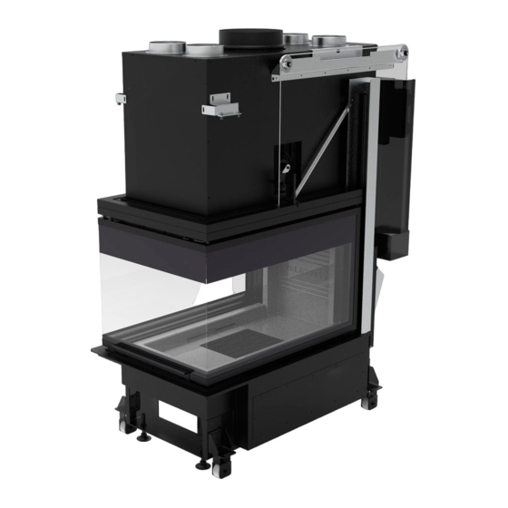
ITALIANO ENGLISH DEUTSCH FRANÇAIS ESPAÑOL CARATTERISTICHE DEL COMBUSTIBILE Caratteristiche del combustibile L’apparecchio va alimentato preferibilmente con legna di faggio / betulla ben stagionata. Ciascun tipo di legna possiede caratteristiche di- verse che influenzano anche il rendimento della combustione. L’uso delle conifere (pino – abete) è sconsigliato: contengono elevate quan- tità... - Page 14 CONOSCERE IL PRODOTTO 4.1 Descrizione Fig. 2 Canalizzazione aria (*) Ingresso aria comburente Maniglia di apertura porta Ventilatore ambiente (*) Vetro porta Automazione porta (**) Griglia focolare Predisposizione canalizzazione aria (*) Cassetto cenere Uscita fumi Maniglia fredda (*) Per modelli V16 - V16 EPLUS Regolazione aria comburente (**) Solo modello V16 EPLUS.
- Page 15 ITALIANO ENGLISH DEUTSCH FRANÇAIS ESPAÑOL 4.2 Dimensioni WT60 3D N16 1240 139,5 166,5 166,5 altezza variabile in funzione dei piedini Dimensioni in mm Fig. 3 004778610 - 16/12/2020...
- Page 16 WT60 3D V16 1247 166,5 139,5 166,5 altezza variabile in funzione dei piedini Dimensioni in mm Fig. 4 004778610 - 16/12/2020...
- Page 17 ITALIANO ENGLISH DEUTSCH FRANÇAIS ESPAÑOL WT60 3D V16 EPLUS 1301 139,5 166,5 166,5 altezza variabile in funzione dei piedini Dimensioni in mm Fig. 5 004778610 - 16/12/2020...
-
Page 18: Caratteristiche Tecniche
4.3 Caratteristiche tecniche WT60 3D WT60 3D V16 EPLUS Classe di appartenenza in riferimento a D.L.G. 186/2017 4 stelle 4 stelle Potenza termica nominale (*) 16,7 16,7 Rendimento 78,7 78,7 Consumo orario di combustibile kg/h 5,14 5,14 Portata dei fumi 16,3 16,3 Emissioni di CO (13% di O2) - Page 19 ITALIANO ENGLISH DEUTSCH FRANÇAIS ESPAÑOL 4.4 Targhetta matricola Palazzetti Lelio S.p.A. - via Roveredo 103 - 33080 Porcia (PN) Combustibile Potenza termica max introdotta Imax Potenza termica nominale Pmax Rendimento alla potenza nominale EFFmax Emissioni di CO alla potenza nominale(13% O2)
-
Page 20: Schema Elettrico
4.5 Schema elettrico WT60 3D V16 USER INTERFACE t° F01/02 +VIO ~220 - 240 Vac ~220 - 240 Vac NOTE:phase protection,added by customer.Do not change polarity! 004726708 - 24/11/2020 Fig. 7 Ventilatore ambiente Sonda fumi Sonda ambiente Pannello comandi 004778610 - 16/12/2020... - Page 21 ITALIANO ENGLISH DEUTSCH FRANÇAIS ESPAÑOL WT60 3D V16 EPLUS BLUE WHITE BROWN WHITE GREEN YELLOW USER INTERFACE POWER NOTE:phase protection,added by customer.Do not change polarity! 004726709 - 24/11/2020 Fig. 8 Sonda fumi Sonda temperatura ambiente Sonda temperature camera di Pannello comandi combustione Motore della porta Nella configurazione 2 il componente n°3...
- Page 22 MOVIMENTAZIONE E • Rimozione dalla paletta di trasporto TRASPORTO Lo smaltimento dei materiali può essere affidato anche a terzi, purché si ricorra sempre a ditte autorizzate al recupero e all’eliminazione dei L’apparecchio viene consegnato completo di materiali in questione. tutte le parti previste: struttura metallica monta- ta e rivestimento interno camera di combustione Attenersi sempre e comunque alle normative in separato.
- Page 23 ITALIANO ENGLISH DEUTSCH FRANÇAIS ESPAÑOL Trasporto dal pavimento al piano fuoco di circa 35-40 cm per facilitarne l'utilizzo. Accertarsi che il carrello sollevatore Per la messa in piano dell'apparecchio usare le abbia una portata superiore al peso apposite viti di regolazione poste sotto i piedi dell’apparecchiatura da sollevare.
-
Page 24: Preparazione Del Luogo Di Installazione
PREPARAZIONE 6.3 Luogo d’installazione DEL LUOGO DI Per le distanze minime che devono essere ri- spettate nel posizionamento dell'apparecchio INSTALLAZIONE rispetto a materiali e oggetti infiammabili fare riferimento alle indicazioni di Fig. 13. Considerazioni generali Nei paragrafi successivi sono riportate alcune indicazioni da rispettare per ottenere il massimo rendimento del prodotto acquistato e il funzio- namento in sicurezza. -
Page 25: Installazione
ITALIANO ENGLISH DEUTSCH FRANÇAIS ESPAÑOL INSTALLAZIONE ciente agire sulle viti di regolazione predisposte sulle gambe. Registrare le viti (Fig. 15: A-vite re- golazione, B-altezza piano fuoco), fino a portare Considerazioni generali il profilo coprimarmo sull'Ecomonoblocco all’al- tezza prevista rispetto al rivestimento, avendo Nei paragrafi successivi sono riportate alcune cura che la base del focolare sia a bolla. -
Page 26: Messa A Terra
7.5 Messa a terra Il rivestimento deve essere realizzato in materiale ignifugo. L’apparecchio è provvisto di vite per attacco equipotenziale atto a ricevere un cavo di sezione da 2,5 mm a 6 mm , da utilizzare per ottenere In presenza di strutture o materiali in- l’equipotenzialità... - Page 27 ITALIANO ENGLISH DEUTSCH FRANÇAIS ESPAÑOL max 45° H=2D L'immagine è puramente indicativa. L’immagine è puramente indicativa. Fig. 17 Fig. 18 7.7 Presa d’aria Il canale da fumo (A - Fig. 18) tra focolare e camino dovrà avere la stessa sezione dell’uscita fumi del L'Ecomonoblocco deve avere il giusto apporto caminetto.
-
Page 28: Collegamento Mandata Aria Calda
7.8 Collegamento mandata aria calda Solo per modelli V16 - V16 EPLUS 7.8.1 Raccordo in controcappa per riscaldamento in unico ambiente Applicare i tubi flessibili (Ø 140 mm) per la distribuzione d’aria calda alle bocchette an- teriori di uscita, sopra la cappa, fissandoli con le apposite fascette. - Page 29 ITALIANO ENGLISH DEUTSCH FRANÇAIS ESPAÑOL ESEMPIO DI CANALIZZAZIONE ARIA (Fig. 24) BM = Bocchetta di mandata a soffitto completa di serranda di taratura 15x15 GT= Griglia di transito sulla parte bassa della porta A+B = GRIGLIE di ripresa aria ambiente con fori da 14 cm, collegate con tubo flessibile al ventila- tore, con o senza griglia fissa, senza serranda C =Apertura di presa aria esterna posizionata...
-
Page 30: Collegamento Elettrico
Prima di costruire la controcappa dovrà essere installata la centralina di comando. Palazzetti non fornisce il cavo di ali- mentazione, la sua realizzazione è a Nel corso della realizzazione della cappa è indi- cura dell’installatore. -
Page 31: Messa In Servizio
ITALIANO ENGLISH DEUTSCH FRANÇAIS ESPAÑOL MESSA IN SERVIZIO 8.3 Montaggio deflettori e O2RING Dopo aver posizionato l’apparecchio è necessario Per la numerazione dei pannelli fare rife- eseguire le seguenti operazioni: rimento al paragrafo "Descrizione e posi- zionamento deflettori" a pagina 31.. Verifica base in refrattario 1) Aprire la porta spingendola verso l'alto. - Page 32 5) Posizionare i pannelli (1) appoggiandoli sugli 8.4 Montaggio refrattario appositi supporti (C) (Fig. 29). 1) Appoggiare lo schienale in refrattario (A) alla parete dell'Ecomonoblocco e farlo delicata- mente scivolare in posizione, centrandolo con le protuberanze (B) presenti nella base in re- frattario (Fig.
-
Page 33: Collegamenti Elettrici
ITALIANO ENGLISH DEUTSCH FRANÇAIS ESPAÑOL 8.5 Collegamenti elettrici 8.5.1 Serie WT60 3D V16 Sonda temperatura ambiente canalizzazione Sonda temperatura camera di combustione Sonda temperatura ambiente Le immagini del prodotto sono puramente indicative Fig. 33 004778610 - 16/12/2020... - Page 34 8.5.2 Serie WT60 3D V16 EPLUS Sonda temperatura ambiente canalizzazione Sonda temperatura camera di combustione Sonda temperatura ambiente Alimentatore Display Le immagini del prodotto sono puramente indicative Fig. 34 004778610 - 16/12/2020...
-
Page 35: Prima Accensione
ITALIANO ENGLISH DEUTSCH FRANÇAIS ESPAÑOL 8.6 Prima accensione L’installazione ed il collegamento elet- trico dell’alimentatore deve essere La prima accensione deve essere esegui- eseguito solo da personale tecnico ta dall'installatore. qualificato. L’alimentatore (A) va posizionato ad Prima della messa in servizio rimuove- almeno 30 cm dal pavimento, in un re gli adesivi e gli imballaggi interni al vano protetto da liquidi, umidità... -
Page 36: Funzionamento
FUNZIONAMENTO 9.2 Ricarica del combustibile Durante il funzionamento, per eseguire la ricarica Accensione del combustibile è necessario seguire la seguen- te procedura: • Aprire la porta scorrevole, utilizzando l’apposito • Aprire lentamente la porta fuoco, onde evitare guanto in dotazione, impugnando la maniglia di creare una depressione d’aria nel focolare, e spingendola verso l’alto oppure agendo sul che provocherebbe una quasi certa fuoriuscita... - Page 37 ITALIANO ENGLISH DEUTSCH FRANÇAIS ESPAÑOL 9.4 Funzionamento versioni WT60 3D • BTicino Living V16 - V16 EPLUS • BTicino Axolute • GEWISS Top System Riscaldamento per convezione forzata. • GEWISS Chorus WT60 3D V16 • VIMAR Idea Versione dotata di un sistema innovativo il quale, tramite il pannello comandi, permette di regolare •...
- Page 38 9.4.2 Descrizione del menù Menu Funzione Descrizione Valori °C Temperatura Visualizzazione della temperatura letta in ambiente Impostazione della velocità del ventilatore dell’aria Ventilazione Off; 1..5; High; Auto ambiente. Schermata 1 ET4W: nome identificativo (personalizzabile da App) AP MODE: modalità funzionamento Wi-Fi xx:xx:xx:xx:xx:xx: Mac Address identificativo Schermata 2 connboxxxx: nome rete Wi-Fi (SSID)
- Page 39 ITALIANO ENGLISH DEUTSCH FRANÇAIS ESPAÑOL 9.4.3 Parametri di funzionamento Il funzionamento dell’apparecchiatura è deter- minato dai parametri di Potenza e Ventilazione impostati dall’utente. Modifica della potenza (per versioni WT60 3D V16 EPLUS) La potenza definisce la quantità di aria combu- rente e quindi incide direttamente anche sui consumi.
- Page 40 10 TELECOMANDO 6) Tasto momentaneamente non abilitato 7) Tasti per impostazione parametri (OPTIONAL) 8) Tasti per impostazione parametri 10.1 Generalità Questo dispositivo consente controllare remoto parametri funzionamento dell’Ecomonoblocco. 10.2 Procedura di abbinamento al pannello di controllo Accedere alla schermata Info sul display del pan- nello di controllo e portarsi sulla schermata Remote: scanning ...
-
Page 41: Pulizia E Manutenzione
ITALIANO ENGLISH DEUTSCH FRANÇAIS ESPAÑOL 11 PULIZIA E MANUTENZIONE Le operazioni di manutenzione devono essere effettuate da parte di un centro di assistenza tecnico autorizzato. Prima di effettuare qualsiasi operazione di manutenzione adottare le seguenti precauzioni: • Assicurarsi che tutte le parti dell'apparecchio siano fredde. •... - Page 42 11.3 Programma di pulizia e manutenzione 11.3.1 Utente OGNI OGNI SETTIMANA 1 MESE ACCENSIONE Braciere / Griglia (Fig. 42) Cassetto / Vano cenere (Fig. 43) Vetro (Fig. 44 - Fig. 45) 11.3.2 Centro di assistenza tecnico abilitato 1 ANNO (*) Guarnizioni porta Cementi e deflettori fumi (fare riferimento al paragrafo "Pulizia cementi e deflettori fumi"...
- Page 43 ITALIANO ENGLISH DEUTSCH FRANÇAIS ESPAÑOL 11.4 Pulizia interna del focolare Prima di effettuare qualsiasi operazione di ma- nutenzione adottare le seguenti precauzioni: 1) Assicurarsi che la griglia (A) (Fig. 42) sia libera da eventuali residui di combustione che pos- sano ostruire il libero passaggio d’aria. Ri- muoverla ed effettuare la pulizia del focolare utilizzando una scopetta (non in dotazione) facendo convogliare i residui della combu-...
-
Page 44: Pulizia Del Vetro
11.5 Pulizia del vetro Non pulire il vetro durante il funzionamento dell'apparecchio e non utilizzare spugne abrasive. Durante le operazioni di pulizia, sostenere la porta con una mano per evitare eccessive sollecitazioni alla struttura. Fare molta attenzione a non urtare il vetro ceramico a causa dell'elevata fragilità del materiale. - Page 45 ITALIANO ENGLISH DEUTSCH FRANÇAIS ESPAÑOL Fig. 45 4) Accompagnare l'anta fino alla completa Fig. 47 chiusura. 5) Spingere con la mano la leva (B) e riportarla Sollevare ed estrarre i deflettori aria combu- nella posizione di blocco (Fig. 46). rente (B), la griglia (C) e il cassetto cenere (D) (Fig.
- Page 46 7) Sfilare ed estrarre i pannelli (4) Fig. 52). Fig. 52 8) Procedere allo stesso modo sul lato opposto (Fig. 53). Fig. 49 4) Sfilare ed estrarre i pannelli (1) (Fig. 50). Fig. 53 9) Effettuata la pulizia rimontare il tutto facendo Fig.
-
Page 47: Demolizione Esmaltimento
ITALIANO ENGLISH DEUTSCH FRANÇAIS ESPAÑOL 12 DEMOLIZIONE E elettriche ed elettroniche, denominate RAEE, promuovendo il reimpiego, il riciclaggio e altre SMALTIMENTO forme di recupero in modo da ridurne la quan- tità da avviare allo smaltimento e migliorando l’intervento dei soggetti che partecipano al ciclo La demolizione e lo smaltimento dell'apparec- chio sono ad esclusivo carico e responsabilità... - Page 48 INDEX User and Installer Installer 1 GENERAL INTRODUCTION Symbols Intended use Purpose and content of the manual Preservation of the manual Update of this manual Overview Compliance Responsibility of the manufacturer Technical assistance and maintenance 1.10 Spare Parts 1.11 Serial identification plate 1.12 Delivery of the appliance 2 SAFETY WARNING Warnings for the installer...
-
Page 49: Handling And Transportation
8.3 Assembly of the deflectors and O-RING 8.4 Assembly of refractory brick 8.5 Electrical connections 8.6 First lighting 9 OPERATION Ignition 9.2 Adding fuel 9.3 Operation version WT60 3D N16 9.4 Operation versions WT60 3D V16 - V16 EPLUS 004778610 - 16/12/2020... - Page 50 10 REMOTE CONTROL (OPTIONAL) 10.1 Overview 10.2 Pairing at the control panel 10.3 Keys 10.4 Changing the power 10.5 Changing the ventilation 10.6 Door opening/closing (where provided) 10.7 Reset the remote control 11 CLEANING AND MAINTENANCE 11.1 Maintenance of the smoke system 11.2 Appliance maintenance 11.3 Cleaning and maintenance program 11.4 Cleaning the inside of the fire box...
-
Page 51: General Introduction
Palazzetti specialised personnel. The installation manual is an integral part of the appliance. Palazzetti reserves the right to change specifi- cations and technical and/or functional charac- Deterioration or loss teristics of the product at any time without prior If necessary, request a further copy from notice. -
Page 52: Responsibility Of The Manufacturer
The following harmonised standards and/or reg- stallation of the appliance cannot be considered ulations have been applied: to be taken on by Palazzetti; it is and remains the responsibility of the installer, who is responsible CPR: for carrying out the checks relating to the flue,... - Page 53 1.12 Delivery of the appliance maintenance The appliance is delivered perfectly packaged and fixed to a wooden platform which allows Palazzetti has a dense network of service centres handling it using fork lift trucks and/or other with specialised, trained and skilled technicians. means.
-
Page 54: Safety Warning
SAFETY WARNING Do not carry out on-the-fly electrical connections with temporary or uninsu- lated cables. Warnings for the installer Check that the earthing of the electri- Observe the prescriptions contained in cal system is efficient. this manual. Before starting the assembly or dis- The instructions for assembly assembly phases of the appliance, and disassembly of the appli-... - Page 55 ITALIANO ENGLISH DEUTSCH FRANÇAIS ESPAÑOL 2.2 Warnings for technical 2.3 Warnings for users maintenance personnel To ensure correct use of the product Maintenance operations must be car- and electronic appliances connected ried out only by authorised and quali- thereto and to prevent accidents, it is important to always follow the instruc- fied personnel.
- Page 56 cooled. responsible must not be carried out by unsupervised children. In case of flue gas leaks in the room or Before performing any type of opera- deflagration detrimental to the device, tion, the user or whoever is operating turn it off, ventilate the room and im- the product must have read and fully mediately contact your installer/service understood the contents of this instal-...
- Page 57 ITALIANO ENGLISH DEUTSCH FRANÇAIS ESPAÑOL Incorrect use of the product or incor- rect maintenance works may create a serious risk of explosion in the combus- tion chamber. Only use the fuel recommended by the manufacturer. The product must never be used as an incinerator. It is prohibited to use benzene, lamp fuel, kerosene, liquid firelighter for wood, ethyl alcohol or similar liquids...
-
Page 58: Fuel Characteristics
FUEL CHARACTERISTICS Fuel characteristics The appliance should preferably be fuelled with well seasoned beech/birch wood. Each type of wood has different characteristics that also affect the combustion efficiency. The use of conifers (pine-fir) is discour- aged: they contain high quantities of resinous substances that quickly clog the flue. - Page 59 ITALIANO ENGLISH DEUTSCH FRANÇAIS ESPAÑOL BECOMING FAMILIAR WITH THE PRODUCT 4.1 Description Fig. 2 Air ducting (*) Combustion air inlet Door opening handle Room fan (*) Door glass Door automation (**) Fire box grate Air ducting fitting (*) Ash drawer Flue gas outlet Cold handle (*) For models V16 - V16 EPLUS...
- Page 60 4.2 Dimensions WT60 3D N16 1240 139,5 166,5 166,5 variable height depending on the feet Dimensions in mm Fig. 3 004778610 - 16/12/2020...
- Page 61 ITALIANO ENGLISH DEUTSCH FRANÇAIS ESPAÑOL WT60 3D V16 1247 166,5 139,5 166,5 variable height depending on the feet Dimensions in mm Fig. 4 004778610 - 16/12/2020...
- Page 62 WT60 3D V16 EPLUS 1301 139,5 166,5 166,5 variable height depending on the feet Dimensions in mm Fig. 5 004778610 - 16/12/2020...
-
Page 63: Technical Features
ITALIANO ENGLISH DEUTSCH FRANÇAIS ESPAÑOL 4.3 Technical features WT60 3D WT60 3D V16 EPLUS Relevant class with reference to Italian Legislative 4 stars 4 stars Decree 186/2017 Rated thermal power (*) 16.7 16.7 Yield 78.7 78.7 Hourly fuel consumption kg/h 5.14 5.14 Fume flow rate... - Page 64 4.4 Serial identification plate Palazzetti Lelio S.p.A. - via Roveredo 103 - 33080 Porcia (PN) Combustibile Potenza termica max introdotta Imax Potenza termica nominale Pmax Rendimento alla potenza nominale EFFmax Emissioni di CO alla potenza nominale(13% O2) COmax mg/Nm Polveri alla potenza nominale(13% O2)
-
Page 65: Wiring Diagram
ITALIANO ENGLISH DEUTSCH FRANÇAIS ESPAÑOL 4.5 Wiring diagram WT60 3D V16 USER INTERFACE t° F01/02 +VIO ~220 - 240 Vac ~220 - 240 Vac NOTE:phase protection,added by customer.Do not change polarity! 004726708 - 24/11/2020 Fig. 7 Room fan Room sensor Flue gas probe Control panel 004778610 - 16/12/2020... - Page 66 WT60 3D V16 EPLUS BLUE WHITE BROWN WHITE GREEN YELLOW USER INTERFACE POWER NOTE:phase protection,added by customer.Do not change polarity! 004726709 - 24/11/2020 Fig. 8 Flue gas probe Motorised door limit switch Combustion chamber temperature Room temperature probe probe Control panel Door motor Room fan In configuration 2 component no.3 (room...
- Page 67 ITALIANO ENGLISH DEUTSCH FRANÇAIS ESPAÑOL HANDLING AND • Removal from the transport pallet TRANSPORTATION Disposal can be entrusted to a third party, provid- ed only companies authorised for the recovery and elimination of the materials in question are The appliance is delivered complete with all used.
- Page 68 Transportation To level the appliance, use the dedicated ad- justment screws located under the feet of the appliance. Make sure that the lifting carriage has a payload higher than the weight of the appliance to be lifted. The full responsi- bility of the lifting of loads lies with the person handling the lifting equipment.
-
Page 69: General Considerations
ITALIANO ENGLISH DEUTSCH FRANÇAIS ESPAÑOL PREPARATION OF THE 6.3 Place of installation INSTALLATION SITE For the minimum distances that must be re- spected when positioning the appliance with respect to flammable materials and objects, refer General considerations to the instructions in Fig. 13. The following paragraphs contain some guide- lines to be followed to obtain the maximum efficiency of the product purchased and to... -
Page 70: Installation
INSTALLATION the screws (Fig. 15: A-adjustment screw, B-fire bed height), until the marble cover profile is brought on the Ecomonoblocco to the required General considerations height with respect to the cladding, making sure that the base of the fire box is level. In the following paragraphs some indications are provided to be respected in order to obtain the maximum performance from the purchased... - Page 71 ITALIANO ENGLISH DEUTSCH FRANÇAIS ESPAÑOL 7.5 Earthing In presence of flammable structures or other materials behind or besides the The appliance is provided with screw for equi- fire box, respect the minimum safety potential coupler that can receive a cable with distances reported on the product cross-section from 2.5 mm to 6 mm...
-
Page 72: Air Intake
max 45° H=2D The image is purely indicative. L’immagine è puramente indicativa. Fig. 17 Fig. 18 7.7 Air intake The fume duct (A - Fig. 18) between the fire box and the fireplace must have the same section The Ecomonoblocco must have the right flow of as the smoke outlet of the fireplace. -
Page 73: Hot Air Delivery Connection
ITALIANO ENGLISH DEUTSCH FRANÇAIS ESPAÑOL 7.8 Hot air delivery connection Only for models V16 - V16 EPLUS 7.8.1 Hood liner fitting for heating in a single environment Apply the flexible pipes (Ø 140 mm) for the distribution of hot air to the front outlet vents, above the hood, securing them with the appro- priate clamps. - Page 74 EXAMPLE OF AIR DUCTING (Fig. 24) BM = Ceiling delivery vent complete with calibra- tion shutter 15x15 GT= Grille on lower part of door A+B = Ambient air intake GRILLES with 14 cm holes, connected to the fan with a flexible hose, with or without fixed grille, without shutter C =External air intake opening located under the hearth, with grille with fixed fins and anti-insect...
-
Page 75: Electrical Connection
For constructing of the hood liner it is recom- accessible after appliance installation as well. mended to use flame-retardant plasterboard . Palazzetti does not provide the power Before creating the hood liner, the control unit must be installed. cord; the installer must provide this. - Page 76 COMMISSIONING 8.3 Assembly of the deflectors and O-RING After positioning the appliance it is necessary to perform the following operations: For the numbering of the panels refer to the paragraph “Description and posi- Check refractory base tioning of the deflectors” on page 76. The refractory base supplied already assembled 1) Open the door by pushing it upwards.
- Page 77 ITALIANO ENGLISH DEUTSCH FRANÇAIS ESPAÑOL 5) Position the panels (1) resting them on the 8.4 Assembly of refractory brick appropriate supports (C) (Fig. 29). 1) Place the refractory back plate (A) on the Eco- monoblocco wall and gently slide it into po- sition, centring it with the protuberances (B) present in the refractory brick base (Fig.
-
Page 78: Electrical Connections
8.5 Electrical connections 8.5.1 Series WT60 3D V16 Ducting ambient temperature probe Combustion chamber temperature probe Room temperature probe Product images are purely indicative Fig. 33 004778610 - 16/12/2020... - Page 79 ITALIANO ENGLISH DEUTSCH FRANÇAIS ESPAÑOL 8.5.2 Series WT60 3D V16 EPLUS Ducting ambient temperature probe Combustion chamber temperature probe Room temperature probe Power supply unit Display Product images are purely indicative Fig. 34 004778610 - 16/12/2020...
-
Page 80: First Lighting
8.6 First lighting The installation and electrical connec- tion of the power supply unit must be The first ignition must be carried out performed strictly by qualified techni- by the installer. cal personnel. The power supply unit (A) must be po- Before commissioning, remove the sitioned at least 30 cm off the floor in stickers and packaging inside the fire... -
Page 81: Operation
• Add small pieces of wood on top of the stack in into the environment. a crossed over-type pattern. • Light the fire-igniter from above. 9.3 Operation version WT60 3D N16 • Close the fire door and make sure it is firmly Natural convection heating. closed. - Page 82 9.4 Operation versions WT60 3D V16 - • BTicino Living V16 EPLUS • BTicino Axolute • GEWISS Top System Forced convection heating. • GEWISS Chorus WT60 3D V16 • VIMAR Idea Version equipped with an innovative system, which allows regulation of the fan through the •...
- Page 83 ITALIANO ENGLISH DEUTSCH FRANÇAIS ESPAÑOL 9.4.2 Description of the menu Menu Function Description Values °C Temperature Display of the room temperature detected Ventilation Fan speed setting of the ambient air. Off; 1..5; High; Auto Screen 1 ET4W: identification name (customisable via App) AP MODE: Wi-Fi operating mode xx:xx:xx:xx:xx:xx: Mac Address identifier Screen 2...
- Page 84 9.4.3 Operating parameters The operation of the appliance is determined by the of Power and Ventilation parameters set by the user. Power modification (for versions WT60 3D V16 EPLUS) The power defines the quantity of combus- tion air and therefore has a direct impact on consumption.
-
Page 85: Remote Control
ITALIANO ENGLISH DEUTSCH FRANÇAIS ESPAÑOL 10 REMOTE CONTROL 8) Keys to set the parameters (OPTIONAL) 10.1 Overview This device allows you to remotely control the operating parameters of the Ecomonoblocco. 10.2 Pairing at the control panel Access the screen Info on the control panel dis- play and navigate on the screen Remote: scanning ... -
Page 86: Cleaning And Maintenance
11 CLEANING AND MAINTENANCE Maintenance operations must be performed by an authorised technical assistance centre. Before performing any maintenance operation, take the following precautions: • Ensure that all appliance parts are cold. • Make sure that the ashes are completely extinguished. •... - Page 87 ITALIANO ENGLISH DEUTSCH FRANÇAIS ESPAÑOL 11.3 Cleaning and maintenance program 11.3.1 User EVERY TIME THE APPLIANCE IS EVERY WEEK 1 MONTH TURNED ON Burn pot / Grate (Fig. 42) Ash drawer / Compartment (Fig. 43) Glass (Fig. 44 - Fig. 45) 11.3.2 Authorised technical service centre 1 YEAR (*) Door seals...
-
Page 88: Cleaning The Inside Of The Fire Box
11.4 Cleaning the inside of the fire box Before performing any maintenance operation, take the following precautions: 1) Make sure that the grate (A) (Fig. 42) is free from any combustion residues that may ob- struct the free passage of air. Remove it and clean the fire box using a hand brush (not supplied) conveying the combustion resi- dues into the ash drawer. -
Page 89: Cleaning The Glass
ITALIANO ENGLISH DEUTSCH FRANÇAIS ESPAÑOL 11.5 Cleaning the glass Do not clean the glass while the appliance is operating and do not use abrasive sponges. During the cleaning operations, support the door with one hand to avoid excessive stress- es to the structure. Be very careful not to strike the ceramic glass as the material is very brittle. - Page 90 Fig. 45 4) Accompany the door until it is completely Fig. 47 closed. 5) Push lever (B and return it to the locked posi- 2) Lift and extract the combustion air deflectors tion (Fig. 46). (B), the grate (C) and the ash drawer (D) (Fig. 48).
- Page 91 ITALIANO ENGLISH DEUTSCH FRANÇAIS ESPAÑOL 7) Remove and extract the panels (4) Fig. 52). Fig. 52 8) Proceed in the same way on the opposite side (Fig. 53). Fig. 49 4) Slide out and extract the panels (1) (Fig. 50). Fig.
-
Page 92: Demolition And Disposal
12 DEMOLITION AND the reuse, recycling and other forms of recovery so as to reduce the quantity to be disposed of DISPOSAL and improving the intervention of the parties involved in the life cycle of such products. The demolition and disposal of the appliance are the sole liability and responsibility of the owner who must act in compliance with the laws in force in their country regarding safety, respect... - Page 93 ITALIANO ENGLISH DEUTSCH FRANÇAIS ESPAÑOL INDICE Utilisateur Installateur Installateur 1 INTRODUCTION Symboles utilisés Destination d’emploi Objet et contenu du manuel Conservation du manuel Mise à jour du manuel Généralités Conformité Responsabilité du fabricant Assistance technique et entretien 1.10 Pièces détachées 1.11 Plaque signalétique 1.12 Livraison de l’appareil...
-
Page 94: Manutention Et Transport
8.3 Montage des déflecteurs et du joint torique 8.4 Montage du réfractaire 8.5 Branchements électriques 8.6 Premier allumage 9 FONCTIONNEMENT Allumage 9.2 Rechargement du combustible 9.3 Fonctionnement version WT60 3D N16 9.4 Fonctionnement versions WT60 3D V16 - V16 EPLUS 004778610 - 16/12/2020... -
Page 95: Télécommande (En Option)
ITALIANO ENGLISH DEUTSCH FRANÇAIS ESPAÑOL 10 TÉLÉCOMMANDE (EN OPTION) 10.1 Généralités 10.2 Procédure de couplage au panneau de contrôle 10.3 Légende boutons 10.4 Modification de la puissance 10.5 Modification de la ventilation 10.6 Ouverture / Fermeture de la porte (si cela est prévu) 10.7 Reset de la télécommande 11 NETTOYAGE ET ENTRETIEN 11.1... - Page 96 Le manuel d’installation fait partie intégrante de spécialisé Palazzetti. l’appareil. Palazzetti se réserve le droit de modifier les spé- Perte ou détérioration cifications et les caractéristiques techniques et/ ou fonctionnelles du produit à tout moment sans Si nécessaire, demander un autre exemplaire à...
-
Page 97: Responsabilité Du Fabricant
être considérée 1.8 Responsabilité du fabricant à la charge de la société Palazzetti ; en effet, celle- ci est et reste à la charge de l’installateur qui est tenu d’effectuer les contrôles relatifs au conduit Avec la livraison du présent manuel,... -
Page 98: Pièces Détachées
Assistance technique et entretien 1.12 Livraison de l’appareil Palazzetti met à disposition un réseau dense de L'appareil est livré parfaitement emballé et fixé centres d’assistance avec des techniciens spécia- à une palette en fois permettant de le déplacer lisés, formés et préparés. -
Page 99: Avertissements Pour La Sécurité
ITALIANO ENGLISH DEUTSCH FRANÇAIS ESPAÑOL AVERTISSEMENTS POUR Vérifier que les prédispositions LA SÉCURITÉ du conduit de fumée et de l'ar- rivée d'air soient conformes au type d'installation. Avertissements pour l'installateur Respecter les consignes indiquées Ne pas effectuer de branchements dans le présent manuel. électriques volants avec des câbles provisoires ou non isolés. - Page 100 2.2 Avertissements pour les 2.3 Avertissements pour l’utilisateur techniciens préposés à la Pour une utilisation correcte du pro- maintenance duit et des équipements électroniques qui y sont connectés et pour prévenir Les opérations de maintenance doivent les accidents, les instructions données être effectuées exclusivement par un dans ce manuel doivent toujours être personnel autorisé...
- Page 101 ITALIANO ENGLISH DEUTSCH FRANÇAIS ESPAÑOL Ne pas jeter d’eau sur l’appareil pendant personnes aient reçu des instructions relatives à l'usage sûr de l'appareil et à la son fonctionnement ou pour éteindre compréhension des dangers afférents. le feu dans le brasier. Les enfants ne doivent pas jouer avec Ne pas utiliser l’appareil comme sup- l’appareil.
- Page 102 • éviter de laisser le produit dans des Tout type d'altération ou de rempla- cement non autorisé de pièces non conditions environnementales dé- originales du produit peut être dange- favorables (humidité, salinité de l'air, mauvais temps, etc.) ; reux pour la sécurité de l'opérateur et décharge l'entreprise de toute respon- •...
- Page 103 ITALIANO ENGLISH DEUTSCH FRANÇAIS ESPAÑOL CARACTÉRISTIQUES DU COMBUSTIBLE Caractéristiques du combustible L’appareil doit être préférablement alimenté par du bois de hêtre / bouleau bien sec. Chaque type de bois possède des caractéristiques spéci- fiques qui influencent aussi le rendement de la combustion. Il est déconseillé...
- Page 104 CONNAÎTRE LE PRODUIT 4.1 Description Fig. 2 Canalisation air (*) Arrivée de l’air de combustion Poignée d'ouverture de la porte Ventilateur ambiant (*) Vitre porte Automatisme porte (**) Grille foyer Préparation de la canalisation d'air (*) Tiroir à cendres Sortie fumée Poignée froide (*) Pour les modèles V16 - V16 EPLUS Réglage de l'air de combustion...
- Page 105 ITALIANO ENGLISH DEUTSCH FRANÇAIS ESPAÑOL 4.2 Dimensions WT60 3D N16 1240 139,5 166,5 166,5 hauteur variable en fonction des pieds Dimensions en mm Fig. 3 004778610 - 16/12/2020...
- Page 106 WT60 3D V16 1247 166,5 139,5 166,5 hauteur variable en fonction des pieds Dimensions en mm Fig. 4 004778610 - 16/12/2020...
- Page 107 ITALIANO ENGLISH DEUTSCH FRANÇAIS ESPAÑOL WT60 3D V16 EPLUS 1301 139,5 166,5 166,5 hauteur variable en fonction des pieds Dimensions en mm Fig. 5 004778610 - 16/12/2020...
-
Page 108: Caractéristiques Techniques
4.3 Caractéristiques techniques WT60 3D WT60 3D V16 EPLUS Classe d'appartenance en référence au D.L.G. 186/2017 4 étoiles 4 étoiles Puissance thermique nominale (*) 16,7 16,7 Rendement 78,7 78,7 Consommation horaire de combustible kg/h 5,14 5,14 Débit des fumées 16,3 16,3 Émissions de CO (13% de O2) mg/Nm... - Page 109 ITALIANO ENGLISH DEUTSCH FRANÇAIS ESPAÑOL 4.4 Plaque signalétique Palazzetti Lelio S.p.A. - via Roveredo 103 - 33080 Porcia (PN) Combustibile Potenza termica max introdotta Imax Potenza termica nominale Pmax Rendimento alla potenza nominale EFFmax Emissioni di CO alla potenza nominale(13% O2)
-
Page 110: Schéma Électrique
4.5 Schéma électrique WT60 3D V16 USER INTERFACE t° F01/02 +VIO ~220 - 240 Vac ~220 - 240 Vac NOTE:phase protection,added by customer.Do not change polarity! 004726708 - 24/11/2020 Fig. 7 Ventilateur ambiant Sonde ambiante Sonde fumées Panneau de commande 004778610 - 16/12/2020... - Page 111 ITALIANO ENGLISH DEUTSCH FRANÇAIS ESPAÑOL WT60 3D V16 EPLUS BLUE WHITE BROWN WHITE GREEN YELLOW USER INTERFACE POWER NOTE:phase protection,added by customer.Do not change polarity! 004726709 - 24/11/2020 Fig. 8 Sonde fumées Sonde de température ambiante Sonde de température chambre de Panneau de commande combustion Moteur de la porte...
- Page 112 MANUTENTION ET • Enlèvement de la palette de transport TRANSPORT L'élimination des matériaux peut également être confiée à des tiers, à condition de s’adresser à des entreprises autorisées à récupérer et à éliminer L'appareil est livré complet avec toutes les par- les matériaux en question.
- Page 113 ITALIANO ENGLISH DEUTSCH FRANÇAIS ESPAÑOL Transport teur du sol (par référence au plan feu) d’environ 35-40 cm pour faciliter son utilisation. S’assurer que le chariot élévateur a Pour la mise à niveau de l’appareil, utiliser les vis une capacité supérieure au poids de de réglage situées sous les pieds de l’appareil.
-
Page 114: Lieu D'installation
PRÉPARATION DU LIEU 6.3 Lieu d’installation D’INSTALLATION Pour les distances minimum à respecter lors du positionnement de l’appareil par rapport aux matériaux et aux objets inflammables, se référer Considérations générales aux indications de Fig. 13. Les paragraphes suivants contiennent quelques instructions à... -
Page 115: Installation
ITALIANO ENGLISH DEUTSCH FRANÇAIS ESPAÑOL INSTALLATION les vis (Fig. 15 : A-vis de réglage, B-hauteur plan feu), jusqu’à ce que le profil de recouvrement du marbre sur l'Ecomonoblocco soit positionné à la Considérations générales hauteur prévue par rapport au revêtement, en s’assurant que la base du foyer soit à... -
Page 116: Mise À La Terre
7.5 Mise à la terre Le revêtement doit être réalisé dans un matériau ignifuge. L’appareil est muni d’une vis pour un raccorde- ment équipotentiel en mesure de recevoir un câble d’une section de 2,5 mm à 6 mm , à utiliser En présence de structures ou de maté- pour obtenir l’équipotentialité... - Page 117 ITALIANO ENGLISH DEUTSCH FRANÇAIS ESPAÑOL max 45° H=2D L’image est purement indicative. L’immagine è puramente indicativa. Fig. 17 Fig. 18 7.7 Prise d’air Le conduit des fumées (A - Fig. 18) entre le foyer et la cheminée devra avoir la même section que L’Ecomonoblocco doit avoir la bonne quantité...
- Page 118 7.8 Raccordement de l’arrivée d’air chaud Uniquement pour les modèles V16 - V16 EPLUS 7.8.1 Raccordement dans l’habillage pour le chauffage dans une seule pièce Appliquer les tuyaux flexibles (Ø 140 mm) pour la distribution d'air chaud vers les bouches avant de sortie, sous la hotte, en les fixant avec les colliers prévus à...
- Page 119 ITALIANO ENGLISH DEUTSCH FRANÇAIS ESPAÑOL EXEMPLE DE CANALISATION DE L'AIR (Fig. 24) BM = Bouche d’arrivée au plafond avec clapet de réglage 15x15 GT = Grille de passage sur la partie inférieure de la porte A+B = GRILLES de prise d’air ambiant avec trous de 14 cm, reliées par un tuyau flexible au ventila- teur, avec ou sans grille fixe, sans clapet C =Ouverture de prise d’air extérieure position-...
-
Page 120: Branchement Électrique
Palazzetti ne fournit pas le câble d’ali- L'unité de commande doit être installée avant la mentation, sa réalisation incombe à construction de l’habillage de la hotte. -
Page 121: Mise En Marche
ITALIANO ENGLISH DEUTSCH FRANÇAIS ESPAÑOL MISE EN MARCHE 8.3 Montage des déflecteurs et du joint torique Après avoir positionné l’appareil, il est nécessaire d’effectuer les opérations suivantes : Pour la numérotation des panneaux, se référer au paragraphe « Description et Contrôle de la base en réfractaire position des déflecteurs »... - Page 122 5) Placer les panneaux (1) en les appuyant sur les 8.4 Montage du réfractaire supports prévus à cet effet (C) (Fig. 29). 1) Appuyer le dosseret en réfractaire (A) à la paroi de l'Ecomonoblocco et le faire délicate- ment glisser en position, en le centrant avec les protubérances (B) présentes à...
-
Page 123: Branchements Électriques
ITALIANO ENGLISH DEUTSCH FRANÇAIS ESPAÑOL 8.5 Branchements électriques 8.5.1 Série WT60 3D V16 Sonde de température environnement canalisation Sonde de température chambre de combustion Sonde de température ambiante Les images du produit sont purement indicatives Fig. 33 004778610 - 16/12/2020... - Page 124 8.5.2 Série WT60 3D V16 EPLUS Sonde de température environnement canalisation Sonde de température chambre de combustion Sonde de température ambiante Alimentateur Afficheur Les images du produit sont purement indicatives Fig. 34 004778610 - 16/12/2020...
-
Page 125: Premier Allumage
ITALIANO ENGLISH DEUTSCH FRANÇAIS ESPAÑOL 8.6 Premier allumage L’installation et le raccordement élec- trique de l'alimentateur doivent obli- Le premier allumage doit être effectué gatoirement être effectués par du per- par l’installateur. sonnel technique qualifié. L’alimentateur (A) doit être placé à 30 Avant la mise en service, retirer les cm au moins du sol, dans un compar- étiquettes et les emballages internes... - Page 126 FONCTIONNEMENT 9.2 Rechargement du combustible Durant le fonctionnement, pour approvisionner Allumage le combustible, suivre la procédure suivante : • Ouvrir lentement la porte du foyer afin d’éviter • Ouvrir la porte coulissante, en utilisant le gant la création d’une dépression d’air dans le foyer fourni à...
- Page 127 ITALIANO ENGLISH DEUTSCH FRANÇAIS ESPAÑOL 9.4 Fonctionnement versions • BTicino Living WT60 3D V16 - V16 EPLUS • BTicino Axolute • GEWISS Top System Chauffage par convection forcée. • GEWISS Chorus WT60 3D V16 • VIMAR Idea Version dotée d’un système innovant qui, à tra- vers le panneau de commande, permet de régler •...
- Page 128 9.4.2 Description du menu Menu Fonction Description Valeurs °C Température Visualisation de la température lue dans la pièce Configuration de la vitesse du ventilateur de l'air Off ; 1..5 ; High ; Ventilation ambiant. Auto Page-écran 1 ET4W : nom d’identification (personnalisable depuis l’App) AP MODE : modalité...
- Page 129 ITALIANO ENGLISH DEUTSCH FRANÇAIS ESPAÑOL 9.4.3 Paramètres de fonctionnement Le fonctionnement de l’appareil est déterminé par les paramètres de Puissance et de Ventilation réglés par l'utilisateur. Modification de la puissance (pour versions WT60 3D V16 EPLUS) La puissance définit la quantité d'air combu- rant et donc a une incidence directe sur les consommations.
- Page 130 10 TÉLÉCOMMANDE (EN OPTION) 7) Touches pour le réglage des paramètres 8) Touches pour le réglage des paramètres 10.1 Généralités dispositif permet contrôler à dis- tance les paramètres de fonctionnement de l’Ecomonoblocco. 10.2 Procédure de couplage au panneau de contrôle Accéder à...
-
Page 131: Nettoyage Et Entretien
ITALIANO ENGLISH DEUTSCH FRANÇAIS ESPAÑOL 11 NETTOYAGE ET ENTRETIEN Les opérations de maintenance doivent être effectuées par un centre d’assistance technique autorisé. Avant d’effectuer toute opération d’entretien, prendre les précautions suivantes : • S'assurer que toutes les parties de l’appareil soient froides. •... - Page 132 11.3 Programme de nettoyage et d’entretien 11.3.1 Utilisateur À CHAQUE TOUTES LES TOUS LES MOIS ALLUMAGE SEMAINES Brasier / Grille (Fig. 42) Tiroir / Compartiment à cendres (Fig. 43) Vitre (Fig. 44 - Fig. 45) 11.3.2 Centre d’assistance technicien autorisé 1 AN (*) Joints porte Ciments et déflecteurs à...
- Page 133 ITALIANO ENGLISH DEUTSCH FRANÇAIS ESPAÑOL 11.4 Nettoyage de l'intérieur du foyer Avant d’effectuer toute opération d’entretien, prendre les précautions suivantes : 1) S’assurer que la grille (A) (Fig. 42) soit libre de tout résidu de combustion pouvant obstruer le passage de l’air. La retirer et effectuer le nettoyage du foyer en utilisant une balayette (non fourni) en faisant convoyer les résidus de la combustion dans le tiroir des cendres.
-
Page 134: Nettoyage De La Vitre
11.5 Nettoyage de la vitre Ne pas nettoyer la vitre pendant le fonctionnement de l’appareil et ne pas utiliser d’éponges abrasives. Pendant les opérations de nettoyage, soutenir la porte avec une main pour éviter des sol- licitations excessives de la structure. Faire très attention de ne pas heurter le verre céramique en raison de la grande fragilité... - Page 135 ITALIANO ENGLISH DEUTSCH FRANÇAIS ESPAÑOL Fig. 45 4) Accompagner le battant jusqu'à fermeture Fig. 47 complète. 5) Pousser le levier (B) avec la main et ramener 2) Soulever et extraire les déflecteurs d'air com- le battant en position de verrouillage (Fig. 46). burant (B), la grille (C) et le tiroir à...
- Page 136 Fig. 51 7) Faire glisser et extraire les panneaux (4) Fig. 52). Fig. 49 4) Faire glisser et extraire les panneaux (1) (Fig. 50). Fig. 52 8) Procéder de la même façon du côté opposé (Fig. 53). Fig. 50 5) Faire glisser et extraire les panneaux (2) (Fig. 51).
-
Page 137: Élimination Des Batteries
ITALIANO ENGLISH DEUTSCH FRANÇAIS ESPAÑOL 12 DÉMOLITION ET appelés DEEE, favorisant la réutilisation, le recy- clage et d’autres formes de valorisation afin de ÉLIMINATION réduire la quantité à envoyer pour élimination et d’améliorer l’intervention des sujets participant au cycle de vie de ces produits. La démolition et la mise au rebut de l’appareil sont exclusivement à... - Page 140 Ankündigung zu ändern, um sie zu verbessern, ohne ihre grundlegenden Eigenschaften zu beeinträchtigen. Palazzetti se réserve le droit de modifi er ses produits à tout moment et sans préavis afi n de les améliorer sans en compromettre les caractéristiques essentielles.
Need help?
Do you have a question about the WT60 3D N16 and is the answer not in the manual?
Questions and answers