Table of Contents
Advertisement
Quick Links
Advertisement
Table of Contents

Subscribe to Our Youtube Channel
Related Manuals for Carlisle Ransburg 9060


Summary of Contents for Carlisle Ransburg 9060
- Page 1 SERVICE MANUAL 9060 Classic High Voltage Controller (HV3 - Handguns) Model: 80130-XXX IMPORTANT: Before using this equipment, carefully read SAFETY PRECAUTIONS and all instructions in this manual. Keep this Service Manual for future reference. CP-13-06-R5 (09/2018) 1 / 34 www.carlisleft.com...
- Page 2 MANUAL CHANGES NOTE: This manual has been changed from revision CP-13-06.4 to revision CP-13-06-R5. Reasons for this change are noted under “Manual Change Summary” inside the back cover of this manual. CP-13-06-R5 (09/2018) 2 / 34 www.carlisleft.com...
-
Page 3: Table Of Contents
CONTENTS CONTENTS SAFETY: Safety Precautions ..............................4 Hazards / Safeguards ............................5 INTRODUCTION: 9-14 General Description ............................... 9 Safety Features ..............................9 Displays ................................. 9 Specifications ..............................10 Controller Features ...............................11 Operator Interface ............................... 12 Switches ................................12 LEDs ..................................12 Buttons ................................12 Connection Interface ............................ -
Page 4: Safety
SAFETY SAFETY SAFETY PRECAUTIONS Before operating, maintaining or servicing any Ransburg WA R N I N G electrostatic coating system, read and understand all of the technical and safety literature for your Ransburg products. † The user MUST read and be familiar with the This manual contains information that is important for you Safety Section in this manual and the Ransburg to know and understand. -
Page 5: Hazards / Safeguards
SAFETY AREA SAFEGUARDS HAZARD Tells where hazards Tells how to avoid the hazard. Tells what the hazard is. may occur. Fire Hazard Spray Area Fire extinguishing equipment must be present in the Improper or inadequate spray area and tested periodically. operation and maintenance procedures will cause a fire Spray areas must be kept clean to prevent the... - Page 6 SAFETY AREA SAFEGUARDS HAZARD Tells where hazards Tells how to avoid the hazard. Tells what the hazard is. may occur. Explosion Hazard Spray Area Improper or inadequate Electrostatic arcing must be prevented. Safe sparking operation and maintenance distance must be maintained between the parts being procedures will cause a coated and the applicator.
- Page 7 SAFETY AREA SAFEGUARDS HAZARD Tells where hazards Tells how to avoid the hazard. Tells what the hazard is. may occur. Spray Area / Electrical Discharge High Voltage There is a high voltage device Parts being sprayed and operators in the spray Equipment that can induce an electrical area must be properly grounded.
- Page 8 SAFETY AREA SAFEGUARDS HAZARD Tells where hazards Tells how to avoid the hazard. Tells what the hazard is. may occur. Electrical Discharge Electrical Unless specifically approved for use in hazardous Equipment locations, the power supply, control cabinet, and all High voltage equipment is utilized in the process.
-
Page 9: Introduction
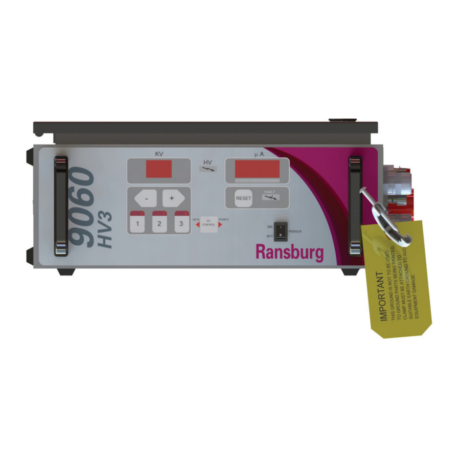
INTRODUCTION GENERAL DESCRIPTION DISPLAYS The Ransburg 9060 High Voltage Controller (80130-XXX) The front panel displays the high voltage set point as well is used to provide high voltage for electrostatic application as a reading of gun current output. The gun current is equipment. -
Page 10: Specifications
INTRODUCTION SPECIFICATIONS Environmental Operating Temperature: 0°C to +40°C 32°F to +104°F Storage and Shipping Temperature: -40°C to +85°C -40°F to +185°F (Allow power supply to go to room temperature before use) Humidity: 95% Non-Condensing Physical Height: 16.5 cm (6.5 inches) Width: 37.8 cm (14.9 inches) Depth:... -
Page 11: Controller Features
INTRODUCTION Figure 2: 9060 High Voltage Controller Features 9060 CONTROLLER FEATURES Description Description kV Display kV Setpoint/Adjust Buttons High Voltage On Indicator Air Flow Switch Hose Connections Reset Button High Voltage Cable Connector µA Display Standard I/O Connector Fault Indicator Fuses On-Off Switch Ground Lug... -
Page 12: Operator Interface
INTRODUCTION OPERATOR INTERFACE Local Mode LED Indicator The local mode LED indicator is a left pointing triangle The 9060 Controller shown in Figure 3, has a simple and is located on the left side the HV control button on the operator interface consisting of 7 LEDs (Light Emitting center of the operator interface. -
Page 13: Connection Interface
INTRODUCTION Left (-)/Right (+) Buttons The left(-)/right(+) buttons in the normal operating mode are used to modify, decrease and increase respectively, the currently selected preset value. If the button is pressed and released, the preset value is changed by 1 kV at a time. -
Page 14: Fuses
INTRODUCTION FUSES High Voltage On (Relay Output, Dry Contact) The “HV on” signal (TB2-4) is a relay controlled signal, Fuses can be configured as either an AC or DC signal using the There are two (2) time delay fuses (250V, 1A, 5mm x Relay Common Input as the signal source. -
Page 15: Installation
INSTALLATION INSTALLATION GENERAL INFORMATION CAUTION The following section contains general information on the † DO NOT locate the Controller near or adjacent installation of 9060 High Voltage Controller. to heat producing equipment such as ovens, high wattage lamps, etc. WA R N I N G The controller may be free standing on any flat surface †... -
Page 16: Electrical Noise
INSTALLATION ELECTRICAL NOISE Electrical noise refers to stray electrical signals in the atmosphere at various signal strengths and frequencies that can affect the operation of equipment. One of the best ways to prevent this is to shield the equipment and cables within a continuous ground envelope, such that any incident noise will be conducted to earth ground before it can affect the circuit conductors. -
Page 17: I/O Connections
INSTALLATION I/O CONNECTIONS For maximum noise immunity, I/O wiring should be run in conduit or cables having a foil shield with an overall braided shield. The foil shield provides 100% shielding, while the braid provides a means of making proper 360° shield terminations at the cable to cabinet connection points. -
Page 18: Safety Ground
INSTALLATION SAFETY GROUND Crimp the appropriate connector onto the ground wire assembly and install from the Controller ground stud, located on the side panel, to a true earth ground. CAUTION † Do NOT rely on the ground connection provided by generators and other portable power generation devices. -
Page 19: Controller Schematic
INSTALLATION WA R N I N G WA R N I N G † ALWAYS ensure that high voltage is OFF before † ALWAYS double check that the Controller is flushing the spray applicator with solvent. NEVER unplugged from its AC outlet before working with flush the spray applicator with high voltage ON, as this any internal wiring. -
Page 20: High Voltage Cable
INSTALLATION source voltage will become available at the output end of NOTE the corresponding contact. Maximum contact ratings for the relays are as follows: † Some codes may require the interlock wiring to be run in conduit. In this case, shielded cable is not necessary, but the conductors used should still meet MAXIMUM CONTACT RATINGS the rating specified above. - Page 21 INSTALLATION 2. Open the Controller cabinet door. 3. The flow switch should have the ground (green) lead connected to the ground screw on the base plate shown in Figure 13. The trigger signal (blue) lead should be connected to the trigger signal input on the J3-5 plug header that is connected to the PC board.
-
Page 22: Operation
OPERATION OPERATION START-UP WA R N I N G After all installation procedures are completed, operation † VERIFY that the gun jumper configuration is set for of the applicator may begin. When the ON-OFF switch is the applicator type that is being used for the system. turned on, the kV display will show the applicator type the 9060 Controller is configured for and the µA (microamp) †... -
Page 23: Lockouts
OPERATION LOCKOUTS There are lockouts that may be done at the PC board (see Figure 18). These lockouts may be used individually or in combination as required. If the jumpers are disconnected, the original functions are re-enabled. After changing any jumpers, the AC power must cycled for the new setting to take affect. -
Page 24: Kv Test Jumper
OPERATION KV TEST JUMPER To assist in testing and troubleshooting, a jumper (J8) has been added to the main PC board. By covering (shorting) both terminals of this jumper, the high voltage of the spray applicator can be activated. Thus, for testing and trou- bleshooting, high voltage output can be obtained without the need to trigger air through the spray applicator. -
Page 25: Setpoint Operations
OPERATION SETPOINT OPERATIONS can then be adjusted between 20 kV and full kV using the + and - buttons on the front panel of the 9060 Controller shown in Figure 16. Single pushes of the + or - buttons Voltage Setpoints will increment or decrement the currently selected preset The voltage on the 9060 High Voltage Controller is adjust- in units of 1. - Page 26 OPERATION BOOT FAULT ILLUMINATES FAUL INDICATOR NOTE AND DISPLAYS “bF” † The ground fault error code displayed on the uA display appears very similar to the boot fault. Verify that the first character appears as a “6” representing the character “G” and not a lowercase “b” for a boot fault. Cable Fault (CF) This fault will occur if high voltage is active and the micro- processor detects that no current is being supplied to the...
- Page 27 OPERATION Over Voltage Fault (OU) OVERLOAD FAULT ILLUMINATES FAUL This fault will occur if the microprocessor detects the unit is INDICATOR AND DISPLAYS “OL” trying to output voltage above the required for the specific applicator type. If this occurs, reset the Controller. If this fault continues to occur, replace the main PC board.
-
Page 28: Maintenance
MAINTENANCE MAINTENANCE TROUBLESHOOTING GUIDE General Problem Possible Cause Solution Blank Display No power Check the power connections and verify they are fully connected and power is available. Power cycle the unit off and back on. Blown fuse Check Fuses and replace if blown using the replacement fuses inside the lid of the unit. - Page 29 MAINTENANCE FAULT TROUBLESHOOTING GUIDE Fault Description Solution Check for loose wiring between the pc board connector Ground Fault (GF) The Ground Fault is typically caused and the high voltage section by pulling on each wire. by a ground connection problem, and Repair if necessary.
- Page 30 MAINTENANCE TROUBLESHOOTING GUIDE General Problem Possible Cause Solution The Voltage Feedback Fault indicates Turn off the voltage controller and remove the high Voltage Cable the cascade drive signal is not present. voltage cable from the voltage controller. Fault (UC) It typically occurs when high voltage is triggered.
-
Page 31: Parts Identification
PARTS IDENTIFICATION PARTS IDENTIFICATION 9060 HIGH VOLTAGE CONTROLLER MODEL IDENTIFICATION* When ordering, use 80130-A1B as indicated by Table A and B. Three digits must follow the basic part number, for example: 80130 - A 1 B TABLE B - PLUG SELECTION TABLE A - MODEL SELECTION BASIC PART NUMBER * Model number and serial number of the voltage controller is located on the... -
Page 32: 9060 High Voltage Controller - Parts List
PARTS IDENTIFICATION 79350-XX 13742-01 / 13742-02 79428-00 72771-06 79390-XX Figure 31: Part Identifications 9060 HIGH VOLTAGE CONTROLLER - PARTS LIST Part No. Description 13742-01 Air Flow Switch (80130-21X, 31X, 51X Units) 13742-02 Air Flow Switch (80130-41X Units) 72771-06 Fuse (250V, 1A, 5mm x 20mm) 79390-01 9060 High Voltage Controller PC Mainboard for 80130-21X 79390-03... -
Page 33: Manual Change Summary
MANUAL CHANGES MANUAL CHANGE SUMMARY CP-13-06-5 - Replaces CP-13-06.4 with the folowing changes: Change Description Page(s) Update to new manual design All Pages Incorporate updated “SAFETY” section CP-13-06-R5 (09/2018) 33 / 34 www.carlisleft.com... - Page 34 This product is covered by Carlisle Fluid Technologies materials and workmanship limited warranty. The use of any parts or accessories, from a source other than Carlisle Fluid Technologies, will void all warranties. For specific warranty information please contact Carlisle Fluid Technologies.
Need help?
Do you have a question about the Ransburg 9060 and is the answer not in the manual?
Questions and answers