Table of Contents
Advertisement
Quick Links
SERVICE MANUAL
EN
Important: Before using this equip-
ment, read all safety precautions and
instructions. Keep for future use.
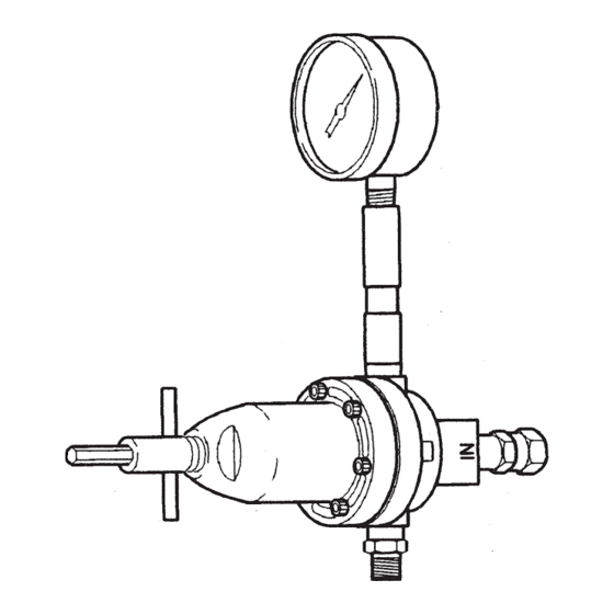
Model HGB-502-1
Regulator Assembly
Only
Model HGB-508-1
Includes HGB-502-1 regulator
plus gauge, riser tube and
fittings.
SPECIFICATIONS:
Height: 5" (excluding adjusting key)
Width: 2-7/8"
Wetted parts: Stainless steel/nylon
Inlet Pressure Regulated
Max . Fluid
Max.
Min. Outlet Press.
Flow
175 psi 50 psi
10-75 psi
8 gal/min.
Maximum temperature 180°F.
INSTALLATION
The HGB regulator is provided with two side
outlet ports and one bottom inlet port, all 3/8"
NPT(F). The regulator may be installed either
vertically or horizontally for flexibility of
installation. In either case, riser and gauge
should be mounted vertically. The HGB-
508 includes gauge, riser tube and fittings
factory installed.
Since the gauge operates on air trapped in
the riser, a rise is always necessary. Any leaks
in riser or gauge connections will permit
this trapped air to escape thus allowing paint
to get into the gauge causing damage.
!
CAUTION
It is recommended that at initial
installation the material supply line
should not be flushed through the
regulator because pipe compound,
chips, scale, etc., may lodge in the
regulator valve assembly.
SB-6-375-R3 (10/2020)
HGB FLUID REGULATORS
See "ACCESSORIES" section for connections
for riser, gauge, adapter and ball valves.
OPERATION
Fluid pressure adjustment is done with a re-
movable key (1). Insert large end of key into
top of regulator. Turn clockwise to increase
fluid pressure, counterclockwise to decrease
fluid pressure.
Fluid pressure adjustment can also be ac-
complished remotely with air control:
1. Turn adjusting key (1) fully counterclock-
wise turning the regulator off.
2. Remove adjusting key (1).
3. Install a 1/4" NPT(M) fitting H-2008 for air
hose connection.
4. Use a regulated air supply to adjust fluid
pressure regulator.
PREVENTIVE MAINTENANCE
Periodic cleaning of regulator with a solvent
compatible with the material being used is
recommended.
To clean material from the regulated material
line and the regulator, these steps should be
followed:
1. Relieve supply line pressure.
2. Using the small end of the adjusting key
(1), engage the regulator and screw it
down tight. This holds the valve off its
Connections
seat. Also, the key may be used in this
3/8"NPT(F)
position to prevent waste from entering
the regulator when spray booth is cleaned.
3. Blow material back through the regulated
line by introducing air pressure into the
line down stream from the regulator. With
spray gun attached, this can be done by
loosening air cap ring on gun, holding
cloth over air cap and pulling trigger. This
forces air in a reverse path through spray
TROUBLESHOOTING
CONDITION
Regulated pressure
creep.
Regulated pressure
drop.
Fluid leakage from
under bonnet.
4. Periodically clean exterior of regulator
PARTS REPLACEMENT
The HGB regulator may be serviced without
removing it from the line.
Remove six socket head cap screws (2) with a
5/32'' hex key. The small end of the adjusting
key (1) may be used for this purpose.
To Replace Diaphragm:
1. The diaphragm socket (B) has an arrow
2. Slip the diaphragm assembly out from
3. Remove nut (A) and pull off diaphragms
4. Apply retaining compound to male
5. Install diaphragm into body by again curl-
6. Slip socket (B) under valve stem nut (C).
7. Reassemble regulator body. Tighten all
To Replace Valve Assembly:
1. Valve assembly (9) can be removed from
2. Install new valve assembly. Tighten valve
CAUSE
Improper seating of valve
stem on seat.
Diaphragm leaking.
Damaged valve seat.
Restriction in main material
line or at valve inlet.
Damaged diaphragm.
Loose cap screws (2).
Damaged diaphragm.
1 / 8
gun and air forces material back through
regulated material line.
with solvent soaked cloth.
Note
Relieve line pressure before servic-
ing regulator.
stamped on top. Curl the edge of
the diaphragm up where the arrows point.
under the valve stem nut (C) so the nut is
released from the socket (B).
(7). Install 2 new diaphragms over thread-
ed end of the socket (B). Convex sides of
each diaphragm must be toward threaded
end.
threads as shown and install nut (A).
ing the edges of the diaphragms.
six cap screws evenly to 65 to 75 in./lbs.
torque.
the body with a 3/4" socket wrench.
assembly to 20 to 25 in./lbs. torque.
CORRECTION
Be sure stem and seat are not
damaged, worn or dirty.
Replace.
Replace seat and stem.
Remove restriction.
Replace.
Tighten all six cap screws evenly
to 65 to 75 in./lbs. torque.
Replace.
www.carlisleft.com
Advertisement
Table of Contents

Subscribe to Our Youtube Channel
Related Manuals for Carlisle DeVILBISS HGB Series


Summary of Contents for Carlisle DeVILBISS HGB Series
- Page 1 SERVICE MANUAL HGB FLUID REGULATORS Important: Before using this equip- See “ACCESSORIES” section for connections gun and air forces material back through for riser, gauge, adapter and ball valves. regulated material line. ment, read all safety precautions and 4. Periodically clean exterior of regulator instructions.
- Page 2 II 2 G Notified body details and role: Element Materials Technology. WN8 9PN UK Lodging of Technical file This Declaration of Conformity Carlisle Fluid Technologies, /incorporation is issued under the sole 320 Phillips Ave., responsiblility of the manufacturer: Toledo, OH 43612...
- Page 3 In this part sheet, the words WARNING, CAUTION and NOTE are used to emphasize important safety information as follows: WARNING NOTE CAUTION Hazards or unsafe practices which Hazards or unsafe practices which could result in severe personal Important installation, operation or could result in minor personal injury, injury, death or substantial property maintenance information.
- Page 4 This end for pressure adjustment HGB-508-1 This end for back HGB-502-1 flushing Torque to •8 65-75 in./lbs. •7 •8 Apply retaining compound on male threads at L.H. assembly Thread Do not over tighten. Max. torque 20-25 in./lbs. Outlet Outlet Parts List Ref.
- Page 5 NOTES SB-6-375-R3 (10/2020) 5 / 8 www.carlisleft.com...
- Page 6 NOTES www.carlisleft.com 6 / 8 SB-6-375-R3 (10/2020)
- Page 7 NOTES SB-6-375-R3 (10/2020) 7 / 8 www.carlisleft.com...
- Page 8 This product is covered by Carlisle Fluid Technologies’ materials and workmanship limited warranty. The use of any parts or accessories, from a source other than Carlisle Fluid Technologies, will void all warranties. Failure to reasonably follow any maintenance guidance provided may invalidate any warranty.
Need help?
Do you have a question about the DeVILBISS HGB Series and is the answer not in the manual?
Questions and answers