Table of Contents
Advertisement
Quick Links
SERVICE MANUAL
EN
Model: 80102-21X (Electric Motor)
IMPORTANT: Before using this equipment, carefully read SAFETY PRECAUTIONS and all
instructions in this manual. Keep this Service Manual for future reference.
CP-13-03-R4 (05/2020)
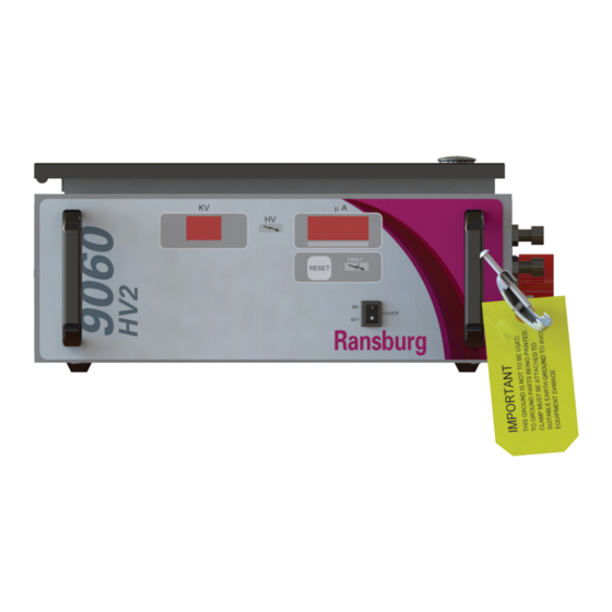
9060 High Voltage Controller for
No.2 Process Handgun
(HV2 - Electric Motor)
1 / 35
www.carlisleft.com
Advertisement
Table of Contents
Troubleshooting

Subscribe to Our Youtube Channel
Related Manuals for Carlisle Ransburg


Summary of Contents for Carlisle Ransburg
- Page 1 SERVICE MANUAL 9060 High Voltage Controller for No.2 Process Handgun (HV2 - Electric Motor) Model: 80102-21X (Electric Motor) IMPORTANT: Before using this equipment, carefully read SAFETY PRECAUTIONS and all instructions in this manual. Keep this Service Manual for future reference. CP-13-03-R4 (05/2020) 1 / 35 www.carlisleft.com...
- Page 2 MANUAL CHANGES NOTE: This manual has been changed from revision CP-13-03.3 to revision CP-13-03-R4. Reasons for this change are noted under “Manual Change Summary” inside the back cover of this manual. CP-13-03-R4 (05/2020) 2 / 35 www.carlisleft.com...
-
Page 3: Table Of Contents
CONTENTS CONTENTS SAFETY: Safety Precautions ..............................4 Hazards / Safeguards ..............................5 INTRODUCTION: 9-13 General Description ..............................9 Safety Features ................................. 9 Displays ..................................9 Specifications ................................10 9060 Controller Features ............................11 Operator Interface ..............................12 Switches .................................. 12 LEDs .................................. -
Page 4: Safety
This information relates to USER SAFETY and safety literature for your equipment, contact your local and PREVENTING EQUIPMENT PROBLEMS. To help you Carlisle Fluid Technologies representative or Carlisle Fluid recognize this information, we use the following symbols. Technologies technical support. -
Page 5: Hazards / Safeguards
SAFETY Return To Contents AREA SAFEGUARDS HAZARD Tells where hazards Tells how to avoid the hazard. Tells what the hazard is. may occur. Fire Hazard Spray Area Fire extinguishing equipment must be present in the Improper or inadequate spray area and tested periodically. operation and maintenance procedures will cause a fire Spray areas must be kept clean to prevent the... - Page 6 SAFETY Return To Contents AREA SAFEGUARDS HAZARD Tells where hazards Tells how to avoid the hazard. Tells what the hazard is. may occur. Explosion Hazard Spray Area Improper or inadequate Electrostatic arcing must be prevented. Safe sparking operation and maintenance distance must be maintained between the parts being procedures will cause a coated and the applicator.
- Page 7 SAFETY Return To Contents AREA SAFEGUARDS HAZARD Tells where hazards Tells how to avoid the hazard. Tells what the hazard is. may occur. Spray Area / Electrical Discharge High Voltage There is a high voltage device Parts being sprayed and operators in the spray Equipment that can induce an electrical area must be properly grounded.
- Page 8 SAFETY Return To Contents AREA SAFEGUARDS HAZARD Tells where hazards Tells how to avoid the hazard. Tells what the hazard is. may occur. Electrical Discharge Electrical Unless specifically approved for use in hazardous Equipment locations, the power supply, control cabinet, and all High voltage equipment is utilized in the process.
-
Page 9: Introduction
9060 Part # Used with No. 2 Gun Type Gun No. 80102-211 Electric Motor, Domestic 19372-XX The Ransburg 9060 High Voltage Controller provides maxi- 80102-212 Electric Motor, European 19372-XX mized operational safety. The protections include detection 80102-213 Electric Motor, China... -
Page 10: Specifications
INTRODUCTION Return To Contents SPECIFICATIONS Environmental Operating Temperature: 0°C to +40°C 32°F to +104°F Storage and Shipping Temperature: -40°F to +185°F -40°F to +185°F Humidity: 95% Non-Condensing Physical Height: 16.5 cm (6.5 inches) Width: 37.8 cm (14.9 inches) Depth: 30.7 cm (12.1 inches) Weight: 10.2 kg (22.5 lbs.) Electrical... -
Page 11: 9060 Controller Features
INTRODUCTION Return To Contents Figure 2: 9060 High Voltage Controller Features (HV2) 9060 CONTROLLER FEATURES Description kV Display High Voltage On Indicator Reset Button µA Display Fault Indicator On-Off Switch High Voltage Cable Connector Fuses Ground Lug AC Inlet Receptacle CP-13-03-R4 (05/2020) 11 / 35 www.carlisleft.com... -
Page 12: Operator Interface
INTRODUCTION Return To Contents OPERATOR INTERFACE BUTTONS Reset Button The 9060 HV2 Controller shown in Figure 3, has a simple The reset button is used to clear fault or overload conditions operator interface consisting of two (2) LED (Light Emitting when the trigger signal if OFF. -
Page 13: Fuses
INTRODUCTION Return To Contents FUSES Fuses There are two (2) time delay fuses (250V, 1A, 5mm x 20mm) installed in fuse holders on the connection interface. They are located directly above the ground lug connection. They are present to provide a measure of safety against power surges through the AC input. -
Page 14: Installation
† As each installation is unique, this information is intended to provide general installation informa- tion for the 9060 Controller. Consult your authorized Ransburg distributor for specific directions pertaining to the installation of your equipment. LOCATION OF THE 9060 Installation of the Controller must be a minimum of 6.1m (20’) from where the spray target is located in accordance... -
Page 15: Safety Ground
INSTALLATION Return To Contents NOTE † All 9060 units (80102-21X) shipped from the fac- tory for either 110 VAC input or 240 VAC input will have a 72771-06, 1 Amp front panel fuses installed. HIGH VOLTAGE CABLE Position the No. 2 Process Handgun in the spray area and route the high voltage cable to the Controller. -
Page 16: Controller Schematic (Hv2)
INSTALLATION Return To Contents Figure 7: Controller Schematic (HV2) CP-13-03-R4 (05/2020) 16 / 35 www.carlisleft.com... -
Page 17: Operation
† DO NOT adjust the gun configuration jumpers. If they display will show the current software revision level as shown are incorrect, contact your Ransburg representative. in Figure 8. These items are displayed for approximately 5 seconds after the board powers up. -
Page 18: Kv Test Jumper
(bF) when the unit is powered on. NOTE † Use Ransburg Calibrated Equipment ONLY for testing and troubleshooting. Refer to the “Accesso- ries” section of this manual for part numbers for test- ing equipment. - Page 19 OPERATION Return To Contents the Fault Indicator on the front of the Controller will light Ground Fault (GF) and a fault code will be displayed on the microamp display. If this fault occurs, the fault indicator on the control unit will Faults can be reset by pressing the Reset button on the front illuminate, a GF indication will show in the uA display.
- Page 20 OPERATION Return To Contents Current Limit Fault (CL) Over Voltage Fault (OU) This fault occurs if the output current exceeds the maxi- This fault will occur if the microprocessor detects the unit is mum current by 20µA. This fault can be caused by ex- trying to output voltage above the required for the specific cessive overspray on the applicator or a paint formulation applicator type.
- Page 21 OPERATION Return To Contents Boot Fault (bF) This fault will occur during the start-up sequence if the No. 2 Handgun on-off switch is in the on position. It is designed to prevent immediate triggering after start-up as the unit should be allowed to enter the “ready” state prior to being triggered.
-
Page 22: Maintenance
Ransburg distributor for specific directions pertaining to the installation of your equipment. Equipment Required: Calibrated Ransburg High Voltage Test Probe and Meter (76652-01) CAUTION † Do not immerse any part of, or all of an assem- KV Output Test Procedure bled applicator in any liquid. - Page 23 Proper troubleshooting should ONLY be accom- electrical shock. plished with specific test equipment by qualified electron- ics technicians or authorized Carlisle Fluid Technologies 3. Attach the appropriate HV cable to the Test Probe representatives. (76652-01), properly ground the probe to a true earth...
-
Page 24: Fault Troubleshooting Guide
MAINTENANCE Return To Contents FAULT TROUBLESHOOTING GUIDE WA R N I N G † Before troubleshooting gun and control unit problems, flush the gun with solvent and purge with air. Some of the tests will require high voltage to be applied to the gun, so the gun must be empty of paint and solvent. - Page 25 MAINTENANCE Return To Contents FAULT TROUBLESHOOTING GUIDE (Cont.) Fault Description Solution Feedback Fault The Feedback Fault indicates there is Securely attach a ground wire to the applicator (FF) no current feedback or it is incorrect. It electrode. typically occurs with the high voltage on. Set the high voltage to maximum and short the KV test jumper.
-
Page 26: General Troubleshooting Guide
MAINTENANCE Return To Contents GENERAL TROUBLESHOOTING GUIDE General Problem Possible Cause Solution No AC power present Ensure voltage across terminals L1 and N of terminal Black Display when block 1TB is between 90 and 264 VAC. from panel switch is turned to the “ON”... - Page 27 MAINTENANCE Return To Contents GENERAL TROUBLESHOOTING GUIDE (Cont.) General Problem Possible Cause Solution Front Panel Display Defective spray gun or high voltage cable. Test gun switch and cable (See Spray Gun’s Service Manual). On, Gun Switch On, No kV at Gun, Motor The connectors J2 and J3 on the PC Properly attach connector J3 and verify that trigger Not Rotating...
-
Page 28: Service Level
† DO NOT attempt to make repairs beyond those described. All others should be made ONLY by NOTE Ransburg service personnel. † It is recommended that the four ON/OFF switch wires be tagged with their respective terminal connec- REPLACEMENT PROCEDURES tions to 1SW before removing. - Page 29 MAINTENANCE Return To Contents 3. Unplug connector 3PL from the top of the high voltage 3. Remove (3) screws from heat sink base and lift the PC multiplier oscillator. board out. 4. Unscrew (4) screws from oscillator board and remove 4.
-
Page 30: 9060 Internal Component Locations
MAINTENANCE Return To Contents (J7) (J3) (J2) (J1) Figure 18: 9060 (80102-21X) Internal Component Locations CP-13-03-R4 (05/2020) 30 / 35 www.carlisleft.com... -
Page 31: Parts Identification
PARTS IDENTIFICATION Return To Contents PARTS IDENTIFICATION 9060 HIGH VOLTAGE CONTROLLER MODEL IDENTIFICATION* When ordering, use 80102-A1B as indicated by Table A and B. Three digits must follow the basic part number, for example: 80102 - 2-1-X TABLE B - PLUG SELECTION TABLE A - MODEL SELECTION BASIC PART NUMBER * Model number and serial number of the voltage controller is located... -
Page 32: Parts Identification
PARTS IDENTIFICATION Return To Contents Figure 19: Parts Identifications 9060 HIGH VOLTAGE CONTROLLER - PARTS LIST Part # Description 72771-06 Fuse (250V, 1A, 5mm x 20mm) 76434-01 Switch, Rocker (On-Off Switch) 80116-28 9060 High Voltage Controller PC Mainboard 79428-00 Power Supply, 24V (24VDC Power Supply 1PS) 19370-XX Cable Assembly, Superflex, (XX denotes cable length) (not shown) 79350-03... -
Page 33: Accessories List
PARTS IDENTIFICATION Return To Contents 9060 HIGH VOLTAGE CONTROLLER - ACCESSORIES LIST Description Part No. 76652-01 HV Probe 76652-02 Meter w/Test Leads 76652-03 Paint Test Probe w/Meter 76652-04 Deluxe Kit (Include HV Probe, Meter w/Test Leads, and Paint Test Probe) LSCH0009 Dielectric Grease (.88 oz tube) 76453-00... -
Page 34: Manual Change Summary
MANUAL CHANGES Return To Contents MANUAL CHANGE SUMMARY CP-13-03-R4 - Replaces CP-13-03.3 with the folowing changes: Change Description Page(s) Update manual to latest design format Add “20868-00 120 Volt Circuit Tester” CP-13-03-R4 (05/2020) 34 / 35 www.carlisleft.com... - Page 35 This product is covered by Carlisle Fluid Technologies materials and workmanship limited warranty. The use of any parts or accessories, from a source other than Carlisle Fluid Technologies, will void all warranties. For specific warranty information please contact Carlisle Fluid Technologies.
Need help?
Do you have a question about the Ransburg and is the answer not in the manual?
Questions and answers