Table of Contents
Advertisement
Quick Links
SERVICE MANUAL
CP-13-04.3
FOR NO. 2 PROCESS HANDGUN
MODEL:
IMPORTANT: Before using this equipment, carefully read SAFETY PRECAUTIONS, starting on
page 1, and all instructions in this manual. Keep this Service Manual for future reference.
CP-13-04.3 (10/2017)
9060 HIGH VOLTAGE
CONTROLLER
(HV2 - AIR MOTOR)
80102-31X (Air Motor)
ATEX APPROVED FOR USE WITH 80086-XX
TM
1 / 29
www.carlisleft.com
Advertisement
Table of Contents

Related Manuals for Carlisle Ransburg 9060 HV2


Summary of Contents for Carlisle Ransburg 9060 HV2
- Page 1 SERVICE MANUAL CP-13-04.3 9060 HIGH VOLTAGE CONTROLLER FOR NO. 2 PROCESS HANDGUN (HV2 - AIR MOTOR) MODEL: 80102-31X (Air Motor) ATEX APPROVED FOR USE WITH 80086-XX IMPORTANT: Before using this equipment, carefully read SAFETY PRECAUTIONS, starting on page 1, and all instructions in this manual. Keep this Service Manual for future reference. CP-13-04.3 (10/2017) 1 / 29 www.carlisleft.com...
- Page 2 MANUAL CHANGES NOTE: This manual has been changed from revision CP-13-04.2 to revision CP-13-04.3. Reasons for this change are noted under “Manual Change Summary” on page 51 of this manual. CP-13-04.3 (10/2017) 2 / 29 www.carlisleft.com...
-
Page 3: Table Of Contents
CONTENTS CONTENTS SAFETY: Safety Precautions ..............................4 Hazards / Safegaurds ............................5 INTRODUCTION: 9-13 General Description ............................... 9 Safety Features ..............................9 Displays ................................. 9 Specifications ..............................10 Controller Features ...............................11 Operator Interface ............................... 12 Switches ................................12 LEDs ..................................12 Buttons ................................ -
Page 4: Safety
SAFETY Return To Contents SAFETY SAFETY PRECAUTIONS Before operating, maintaining or servicing any Ransburg WA R N I N G electrostatic coating system, read and understand all of the technical and safety literature for your Ransburg products. † The user MUST read and be familiar with the This manual contains information that is important for you Safety Section in this manual and the Ransburg to know and understand. -
Page 5: Hazards / Safegaurds
SAFETY Return To Contents AREA SAFEGUARDS HAZARD Tells where hazards Tells how to avoid the hazard. Tells what the hazard is. may occur. Fire Hazard Spray Area Fire extinguishing equipment must be present in the Improper or inadequate spray area and tested periodically. operation and maintenance procedures will cause a fire Spray areas must be kept clean to prevent the... - Page 6 SAFETY Return To Contents AREA SAFEGUARDS HAZARD Tells where hazards Tells how to avoid the hazard. Tells what the hazard is. may occur. Explosion Hazard Spray Area Improper or inadequate Electrostatic arcing must be prevented. Safe sparking operation and maintenance distance must be maintained between the parts being procedures will cause a coated and the applicator.
- Page 7 SAFETY Return To Contents AREA SAFEGUARDS HAZARD Tells where hazards Tells how to avoid the hazard. Tells what the hazard is. may occur. Spray Area / Electrical Discharge High Voltage There is a high voltage device Parts being sprayed and operators in the spray Equipment that can induce an electrical area must be properly grounded.
- Page 8 SAFETY Return To Contents AREA SAFEGUARDS HAZARD Tells where hazards Tells how to avoid the hazard. Tells what the hazard is. may occur. Electrical Discharge Electrical Unless specifically approved for use in hazardous Equipment locations, the power supply, control cabinet, and all High voltage equipment is utilized in the process.
-
Page 9: Introduction
INTRODUCTION Return To Contents INTRODUCTION GENERAL DESCRIPTION provide a controlled output load curve, which limits the high voltage output to safe levels while monitoring control and The Ransburg No. 2 Handgun Process feedback signals for unsafe conditions. Maximum opera- tional safety is obtained when the correct applicator settings The No. -
Page 10: Specifications
INTRODUCTION Return To Contents SPECIFICATIONS Environmental Operating Temperature: 0°C to +40°C Storage and Shipping Temperature: -40°C to +85°C (Allow power supply to go to room temperature before use) Humidity: 95% Non-Condensing Physical Height: 16.5 cm (6.5 inches) Width: 37.8 cm (14.9 inches) Depth: 30.7 cm (12.1 inches) Weight:... -
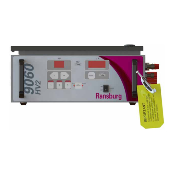
Page 11: Controller Features
INTRODUCTION Return To Contents Figure 2: 9060 High Voltage Controller Features 9060 CONTROLLER FEATURES Description Description kV Display “One Touch” kV Setpoint Buttons High Voltage On Indicator kV Setpoint/Adjust Buttons Reset Button High Voltage Cable Connector µA Display Fuses Fault Indicator Ground Lug On-Off Switch AC Inlet Receptacle... -
Page 12: Operator Interface
INTRODUCTION Return To Contents OPERATOR INTERFACE LOCAL Mode LED Indicator The LOCAL mode LED indicator is a left pointing triangle and is located on the left side the HV control button on the The 9060 Controller shown in Figure 3, has a simple operator center of the operator interface. -
Page 13: Connection Interface
INTRODUCTION Return To Contents Reset Button The reset button is used to clear fault or overload conditions. This will NOT prevent any other active fault conditions from triggering a new fault. HV Control Button This button, shown in the center of Figure 3, is not functional for handgun units. -
Page 14: Installation
INSTALLATION Return To Contents INSTALLATION GENERAL INFORMATION CAUTION The following section contains general information on the † DO NOT locate the Controller near or adjacent installation of 9060 High Voltage Controller. to heat producing equipment such as ovens, high wattage lamps, etc. WA R N I N G AC INPUT CONNECTIONS †... -
Page 15: Safety Ground
INSTALLATION Return To Contents HIGH VOLTAGE CABLE SIDE VIEW Position the No. 2 Process Handgun in the spray area and route the high voltage cable to the Controller. The cable should be routed so that it is not damaged by foot and vehicle traffic and also so that is not close to areas of high temperature (129°F+). -
Page 16: Controller Schematic
INSTALLATION Return To Contents Figure 7: Controller Schematic CP-13-04.3 (10/2017) 16 / 29 www.carlisleft.com... -
Page 17: 2 Process Handgun Trigger Signal
INSTALLATION Return To Contents NO. 2 PROCESS HANDGUN TRIGGER SIGNAL Ground Screw The No. 2 Process Handgun uses a flow switch (13742- 02) to provide the trigger signal. The listed flow switch is mounted inside the 9060 Controller chassis via the Air Flow Switch Connector on the side panel. -
Page 18: Operation
OPERATION Return To Contents OPERATION START-UP WA R N I N G After all installation procedures are completed, operation † USE ONLY the gun type configuration for the No. of the applicator may begin. When the ON-OFF switch is 2 Process Handgun. Using the wrong configuration turned on, the kV display will show the applicator type the may allow for operation outside the recommended 9060 Controller is configured for and the µA (microamp) -
Page 19: Lockouts
OPERATION Return To Contents LOCKOUTS There are lockouts that may be done at the PC board (see Figure 13). These lockouts may be used individually or in combination as required. If the jumpers are disconnected, the original functions are re-enabled. After changing any jumpers, the AC power must cycled for the new setting to take affect. -
Page 20: Kv Test Jumper
OPERATION Return To Contents KV TEST JUMPER To assist in testing and troubleshooting, a jumper (J8) has been added to the main PC board. By covering (shorting) both terminals of this jumper, the high voltage of the spray applicator can be activated. Thus, for testing and troubleshooting, high voltage output can be obtained without the need to trigger air through the spray applicator. -
Page 21: Setpoint Operations
OPERATION Return To Contents SETPOINT OPERATIONS Adjusting Presets To adjust one of the preset setpoints, ensure the No. 2 Voltage Setpoints Handgun is off in LOCAL mode and select the desired The voltage on the 9060 High Voltage Controller is setpoint by pressing the corresponding setpoint button. - Page 22 OPERATION Return To Contents Cable Fault (CF) Overload Fault (OL) This fault will occur if high voltage is active and the This fault will occur if the overload feature is active (see microprocessor detects that no current is being supplied ‘Overload Activation”...
- Page 23 OPERATION Return To Contents VOLTAGE CABLE FAULT ILLUMINATES FEEDBACK FAULT ILLUMINATES FAUL FAUL INDICATOR AND DISPLAYS “UC” INDICATOR AND DISPLAYS “FF” Figure 24: Feedback Fault Display Figure 22: Voltage Cable Fault Display Over Voltage Fault (OU) Boot Fault (bF) This fault will occur if the microprocessor detects the unit is This fault will occur during the start-up sequence if an trying to output voltage above the required for the specific active trigger signal is present.
-
Page 24: Maintenance
MAINTENANCE Return To Contents MAINTENANCE MAINTENANCE TROUBLESHOOTING GUIDE General Problem Possible Cause Solution Blank Display Check the power connections and verify they are No power fully connected and power is available. Power cycle the unit off and back on. Check Fuses and replace if blown using the Blown fuse replacement fuses inside the lid of the unit. - Page 25 MAINTENANCE Return To Contents FAULT TROUBLESHOOTING GUIDE Fault Description Solution The Over Load Fault indicates the current This may indicate the paint conductivity is too high Over-Load output exceeded overload (resistance too low) or the outside of the applicator is Fault (OL) threshold.
-
Page 26: Parts Identification
PARTS IDENTIFICATION Return To Contents PARTS IDENTIFICATION 9060 HIGH VOLTAGE CONTROLLER MODEL IDENTIFICATION* When ordering, use 80102-A1B as indicated by Table A and B. Three digits must follow the basic part number, for example: 80102 - A 1 B TABLE B - PLUG SELECTION TABLE A - MODEL SELECTION BASIC PART NUMBER * Model number and serial number of the voltage controller is located on the left... -
Page 27: 9060 High Voltage Controller - Parts List
PARTS IDENTIFICATION Return To Contents 79350-01 13742-02 79428-00 72771-06 79390-03 76434-01 Figure 26: Part Identifications 9060 HIGH VOLTAGE CONTROLLER - PARTS LIST Part No. Description 13742-02 Air Flow Switch (1.0 - 2.0 SCFM) 72771-06 Fuse (250V, 1A, 5mm x 20mm) 79390-03 9060 High Voltage Controller PC Mainboard 20988-XX... -
Page 28: Manual Change Summary
MANUAL CHANGES Return To Contents MANUAL CHANGE SUMMARY CP-13-04.3 - Replaces CP-13-04.2 with the folowing changes: Previous Current Change Description Page(s) Page(s) Update to new manual design All Pages CP-13-04.3 (10/2017) 28 / 29 www.carlisleft.com... - Page 29 Ransburg products are covered by Carlisle Fluid Technologies materials and workmanship limited warranty. The use of any parts or accessories, from a source other than Carlisle Fluid Technologies, will void all warranties. For specific warranty information please refer to the warranty document supplied with your product, call our Technical Support, or contact the closest Carlisle Fluid Technologies location listed below.
Need help?
Do you have a question about the Ransburg 9060 HV2 and is the answer not in the manual?
Questions and answers