Table of Contents
Advertisement
Quick Links
Service Manual
EN
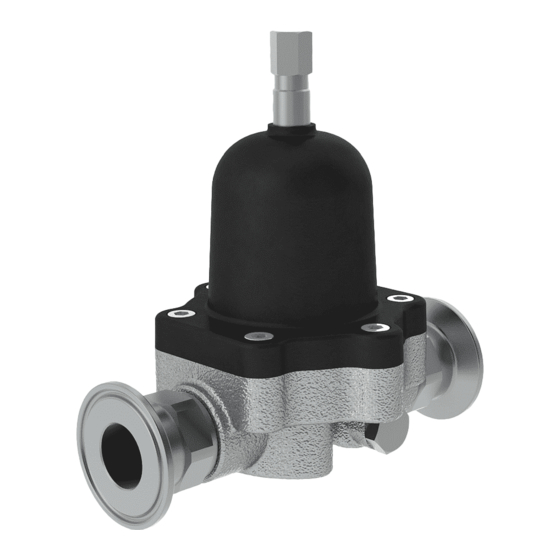
Back Pressure Regulator
It is the Customer's responsibility to have all operators and service personnel read and understand this
Contact your local Carlisle Fluid Technologies representative for additional copies of this manual.
READ ALL INSTRUCTIONS BEFORE OPERATING THIS PRODUCT
77-3247 R2.2
(Low Shear 3/4")
• 107757
15
• 107758
Pilot Control
• 107760 Pilot Control
(Flushable)
IMPORTANT! DO NOT DESTROY
manual.
bar
www.carlisleft.com
Advertisement
Table of Contents

Subscribe to Our Youtube Channel
Related Manuals for Carlisle Binks 107757


Summary of Contents for Carlisle Binks 107757
- Page 1 IMPORTANT! DO NOT DESTROY It is the Customer's responsibility to have all operators and service personnel read and understand this manual. Contact your local Carlisle Fluid Technologies representative for additional copies of this manual. READ ALL INSTRUCTIONS BEFORE OPERATING THIS PRODUCT 77-3247 R2.2...
-
Page 2: Eu Declaration Of Conformity
Providing all conditions of safe use / installation stated within the product manuals have been complied with and also installed in accordance with any applicable local codes of practice. Director of Sales (EMEA) D Smith Signed for and on behalf of Carlisle Fluid Technologies UK Ltd: 27/6/18 Bournemouth,BH11 9LH,UK 77-3247 R2.2... - Page 3 In this part sheet, the words WARNING, CAUTION and NOTE are used to emphasize important safety information as follows: WARNING CAUTION NOTE Hazards or unsafe practices which could result Hazards or unsafe practices which could result in Important installation, operation or severe personal injury, death or substantial in minor personal injury, product or property maintenance information.
-
Page 4: Specification
Specification 107757 Manual Control 3-15 bar Ideal Working Range 2-30 l/min Max. Static Pressure 25 bar Wetted Material 300 Series ST ST and F.E.P. 107758 / 107760 Pilot Control 3-15 bar Ideal Working Range 2-30 l/min Max. Static Pressure 25 bar Wetted Material 300 Series ST ST and F.E.P. - Page 5 Dimensions 1/2" A/F Hexagon Pilot Air Connection 77-3247 R2.2 www.carlisleft.com 5/16...
-
Page 6: Model Selection
Model Selection 107757 Basic Part Number Inlet Fitting Outlet Fitting 107757 - Manual Control 107758 - Pilot Control R, S, T etc. R, S, T etc. 107760 - Pilot Control (Flushable) Outlet Fitting Inlet Fitting Inlet / Outlet Fitting Selection Table Remarks Suffix Part No. -
Page 7: Installation
Installation Outlet Inlet Connect the unit into the paint system pipework in the direction indicated by the arrow on the valve body. Always connect the unit using the correct fittings /gaskets and if a threaded fitting is used a suitable thread compatible sealant. A pressure gauge should be mounted directly into the pipework on the inlet side of the unit to allow precise adjustment for the regulated back pressure. - Page 8 Installation The back pressure regulator is tested with demineralised water, therefore the fluid chamber should be flushed with suitable material prior to use. Note: Before attempting any maintenance ensure that all relevant directions for working safety are followed. If circulating system pressure testing is carried out with the back pressure regulator in circuit, the fluid test pressure must not exceed 25 bar and the back pressure valve must ‘be unloaded’...
- Page 9 Installation Following pressure testing and flushing procedures the diaphragms should be examined and replaced if necessary to ensure the integrity of the unit prior to use in production. Turning the main adjusting screw clockwise will increase the spring pressure on the unit and therefore the fluid back pressure on the paint system.
- Page 10 Parts List Manual Assembly ITEM PART NUMBER DESCRIPTION 0115-010600 1/4" BSPT PLUG 160186 SPRING 161982 Ø19.6 x 2.4 O-RING 163951 M6 x 16 CAP HEAD SCREW 164838 No2 x 4.5 RIVET 185010 .75 BPR BUTTON 192840 NAMEPLATE 192469 SPRING DISC 193139 BASE - MACHINING 193140...
-
Page 11: Manual Assembly
Manual Assembly GREASE LOCTITE TORQUE 77-3247 R2.2 www.carlisleft.com 11/16... - Page 12 Parts List Pilot Assembly ITEM PART NUMBER DESCRIPTION 1/4" BSPT PLUG 0115-010600 (107758 ONLY) 161982 Ø19.6 x 2.4 O-RING 163921 M6 x 25 CAP HEAD SCREW 164838 No2 x 4.75 RIVET 165542 M6 x 12 SCREW 192147 NAMEPLATE 192577 DIAPHRAGM - PILOT 174647 1/8R-4mm PUSH IN ELBOW...
-
Page 13: Pilot Assembly
Pilot Assembly GREASE LOCTITE TORQUE 77-3247 R2.2 www.carlisleft.com 13/16... -
Page 14: Assembly Procedure
Assembly Procedure The back pressure regulator can be serviced and maintained without removing the unit from the paint pipework. Fully unscrew the adjusting screw to remove all paint line pressure (or exhaust the compressed air pilot supply) Isolate the unit from the paint system pipework (and compressed air supply if applicable) Position a ‘drip tray’... -
Page 15: Spare Parts List
Spare Parts List Spare Parts Kit to suit 107757 250674 ITEM PART NO. DESCRIPTION REMARKS 193233 Diaphragm (Composite) Fluid Spare Parts Kit to suit 107758 / 107760 250675 ITEM PART NO. DESCRIPTION REMARKS 193233 Diaphragm (Composite) Fluid 192577 Diaphragm 77-3247 R2.2 www.carlisleft.com 15/16... - Page 16 WARRANTY POLICY This product is covered by Carlisle Fluid Technologies’ materials and workmanship limited warranty. The use of any parts or accessories, from a source other than Carlisle Fluid Technologies, will void all warranties. Failure to reasonably follow any maintenance guidance provided, may invalidate any warranty.
Need help?
Do you have a question about the Binks 107757 and is the answer not in the manual?
Questions and answers