Table of Contents
Advertisement
Quick Links
SERVICE MANUAL
EN
Model: 80143-XXX
IMPORTANT: Before using this equipment, carefully read SAFETY PRECAUTIONS and all
instructions in this manual. Keep this Service Manual for future reference.
CP-13-01-R5 (10/2019)
9060 Power Supply Kit For
80104 External Cascade
for use with Esta-Quick Applicator AEMD600 (ATEX Approved)
80146-XXX
for use with Evolver 560SE (Non-Approved)
1 / 24
www.carlisleft.com
Advertisement
Table of Contents

Related Manuals for Carlisle Ransburg 9060


Summary of Contents for Carlisle Ransburg 9060
- Page 1 SERVICE MANUAL 9060 Power Supply Kit For 80104 External Cascade Model: 80143-XXX for use with Esta-Quick Applicator AEMD600 (ATEX Approved) 80146-XXX for use with Evolver 560SE (Non-Approved) IMPORTANT: Before using this equipment, carefully read SAFETY PRECAUTIONS and all instructions in this manual. Keep this Service Manual for future reference. CP-13-01-R5 (10/2019) 1 / 24 www.carlisleft.com...
- Page 2 MANUAL CHANGES NOTE: This manual has been changed from revision CP-13-01.4 to revision CP-13-01-R5. Reasons for this change are noted under “Manual Change Summary” inside the back cover of this manual. CP-13-01-R5 (10/2019) 2 / 24 www.carlisleft.com...
-
Page 3: Table Of Contents
CONTENTS CONTENTS SAFETY: Safety Precautions ..............................4 Hazards / Safeguards ..............................5 INTRODUCTION: 9-14 General Description ..............................9 9060 Power Supply Kit Part Structure ........................10 Specifications ................................11 80100 Cascade Control Unit Features ........................12 80120 Cascade Control Unit Features ........................13 80104 Cascade Control Unit Features ........................ -
Page 4: Safety
This information relates to USER SAFETY and safety literature for your equipment, contact your local and PREVENTING EQUIPMENT PROBLEMS. To help you Carlisle Fluid Technologies representative or Carlisle Fluid recognize this information, we use the following symbols. Technologies technical support. -
Page 5: Hazards / Safeguards
SAFETY AREA SAFEGUARDS HAZARD Tells where hazards Tells how to avoid the hazard. Tells what the hazard is. may occur. Fire Hazard Spray Area Fire extinguishing equipment must be present in the Improper or inadequate spray area and tested periodically. operation and maintenance procedures will cause a fire Spray areas must be kept clean to prevent the... - Page 6 SAFETY AREA SAFEGUARDS HAZARD Tells where hazards Tells how to avoid the hazard. Tells what the hazard is. may occur. Explosion Hazard Spray Area Improper or inadequate Electrostatic arcing must be prevented. Safe sparking operation and maintenance distance must be maintained between the parts being procedures will cause a coated and the applicator.
- Page 7 SAFETY AREA SAFEGUARDS HAZARD Tells where hazards Tells how to avoid the hazard. Tells what the hazard is. may occur. Spray Area / Electrical Discharge High Voltage There is a high voltage device Parts being sprayed and operators in the spray Equipment that can induce an electrical area must be properly grounded.
- Page 8 SAFETY AREA SAFEGUARDS HAZARD Tells where hazards Tells how to avoid the hazard. Tells what the hazard is. may occur. Electrical Discharge Electrical Unless specifically approved for use in hazardous Equipment locations, the power supply, control cabinet, and all High voltage equipment is utilized in the process.
-
Page 9: Introduction
INTRODUCTION INTRODUCTION GENERAL DESCRIPTION The Ransburg Spray Process a high voltage ON indicator, a cable fault indicator, and a The Ransburg Spray Process is an air atomized method current overload indicator and reset switch. Additionally, for applying coatings to objects electrostatically. This output terminals are provided for remote overload reset, system applies a high voltage DC charge to the applicator nozzle electrode, creating an electrostatic field between the... -
Page 10: 9060 Power Supply Kit Part Structure
INTRODUCTION The 9060 Power Supply Kit is available for automatic applicators as follows: 9060 POWER SUPPLY KIT PART STRUCTURE 80143-ABC (Atex approved when used with 80146-ABC (non- approved when used with AEMD600)-Esta-Quick AA13901X) Evolver 560SE A-Unit Power Type A-Unit Power Type -1 For 110/120 V Input Power (Domestic) 10” Rack -1 For 110/120 V Input Power (Domestic) 10” Rack -2 For 220/240 V Input Power (European) 10”Rack... -
Page 11: Specifications
INTRODUCTION SPECIFICATIONS Physical - 10” Rack 9060 P/N 80120-31X Height: 132mm (5.2 inches) Width: 429mm (16.9 inches) (483mm ear to ear) (19 inches) Depth: 308mm (12.1 inches) Weight: 6.8 kg (15.1 lbs.) Physical - 19” Box 9060 P/N 80100-31X Height: 16.5 cm (6.5 inches) Width: 37.8 cm (14.9 inches) -
Page 12: 80100 Cascade Control Unit Features
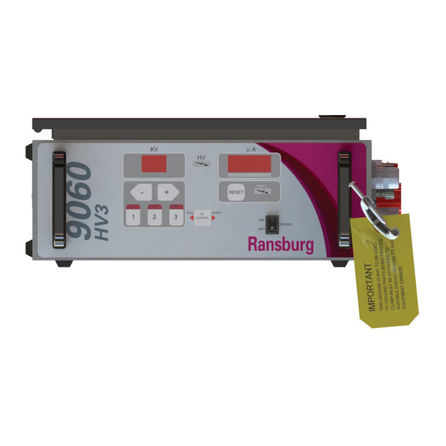
INTRODUCTION Figure 1: 80100 Cascade Control Unit Features 80100 CASCADE CONTROL UNIT FEATURES Item # Description Kilovolt Display Micro Amp Display High Voltage On Indicator Unit ON/OFF Switch Set Point Adjust Buttons Fault Indicator Manual Reset Pad External Wiring Grommet Fuse Low Voltage Cable Connector AC Inlet Receptacle Ground Wire Assembly CP-13-01-R5 (10/2019) -
Page 13: 80120 Cascade Control Unit Features
INTRODUCTION Figure 2: 80120 Cascade Control Unit Features 80120 CASCADE CONTROL UNIT FEATURES Item # Description Kilovolt Display Micro Amp Display High Voltage On Indicator Unit ON/OFF Switch Set Point Adjust Buttons Fault Indicator Manual Reset Pad External Wiring Grommet Fuse Low Voltage Cable Connector AC Inlet Receptacle Ground Wire Assembly CP-13-01-R5 (10/2019) -
Page 14: 80104 Cascade Control Unit Features
INTRODUCTION Figure 3: 80104 Cascade Control Unit Features 80104 CASCADE CONTROL UNIT FEATURES Item # Description Low Voltage Cable Connector Ground Lug Connector Cascade High Voltage Connection Ground Wire Assembly CP-13-01-R5 (10/2019) 14 / 24 www.carlisleft.com... -
Page 15: Atex
ATEX EUROPEAN ATEX DIRECTIVE 2014/34/EU, ANNEX II, 1.0.6 The following instructions apply to equipment covered Aggressive substances: e.g. acidic liquids or gases by certificate number Sira 11ATEX5240X: that may attack metals, or solvents that may affect polymeric materials. 1. The equipment may be used with flammable gases and vapors with apparatus groups II and with temperature Suitable precautions: e.g. -
Page 16: Labels
ATEX 9060 Cascade Low Voltage Control Unit Kit ATEX Product 80143-XXX Marking Definitions Ex Certificate Number: Sira 11ATEX5240X Sira = Notified Body performing EC-type examination 11 = Year of certification ATEX = Reference to ATEX Directive 5 = Protection Concept Code (Code 5 is titled Encapsulation) 240 = Document serial number X = Special conditions for safe use apply Label 80108 Product Marking II 2 G Ex = Specific marking of explosive protection II = Equipment Group hazardous area characteristics 2 = Equipment Category... -
Page 17: Installation
INSTALLATION INSTALLATION Refer to CP-13-05 or CP-13-02 (Included with Your Kit) for Control Unit Installation Instructions. WA R N I N G † The 9060 Controller MUST be located outside of the hazardous area. † The User MUST read and be familiar with the “Safety”... -
Page 18: Typical Installation Schematics
INSTALLATION 10” VERSION 80120-X1X 19” VERSION 80100-X1X Figure 4: Typical Installation 80143-XXX TYPICAL INSTALLATION 80143-XXX Item # Description 9060 Low Voltage Unit AEMD-600 Unit (Atex Approved) WITH MACHINE ADAPTER AEMD-4500-6 A10560-XXD High Voltage Cable 80104-01 External Cascade 79338-XX Low Voltage Cable Booth Wall Cascade Ground Connection Cascade Separate True Earth Ground Control Unit Separate True Earth Ground CP-13-01-R5 (10/2019) 18 / 24 www.carlisleft.com... -
Page 19: High/Low Voltage Cables
INSTALLATION CASCADE GROUND CONNEC- TION APPLICATOR END CASCADE END Figure 5: High Voltage Cable A10560-XXD CONNECTION-CASCADE END CONNECTION-CONTROL UNIT CABLE BOOT Figure 6: Low Voltage Cable 79338-XX CP-13-01-R5 (10/2019) 19 / 24 www.carlisleft.com... - Page 20 INSTALLATION HIGH VOLTAGE CABLE TO CASCADE CONNECTION Strain Relief Insert the grounded cable end of the high voltage cable and Before tightening the cable strain relief, assure the cable the associated connector parts into the external cascade is fully inserted and seated into the bottom of the high in the order shown.
-
Page 21: Operation / Maintenance
OPERATION/MAINTENANCE OPERATION Refer to CP-13-02 or CP-13-05 (Included with Your Kit) for Operation Instructions and Procedures. WA R N I N G † The user MUST read and be familiar with the SAFETY PRECAUTIONS and SAFETY SECTIONS of this manual and the Ransburg safety literature therein identified BEFORE OPERATING the 9060 Cascade control unit. -
Page 22: Parts Identification
PARTS IDENTIFICATION PARTS IDENTIFICATION Refer to CP-13-02 or CP-13-05 (Included in Your kit) for Spare parts available. 80104-01 EXTERNAL CASCADE COMPONENTS Item # Part # Description 80074-00 COUPLER, CABLE 7296-00 NUT, CABLE PLUG 80073-00 RELIEF, STRAIN 8521-06F SET SCREW 80104-01 ASSEMBLY, EXTERNAL (includes item 6) 79350-01 SUB-ASSEMBLY, CASCADE * Not included with the 80104-01 Assembly (must be ordered separately) CP-13-01-R5 (10/2019) 22 / 24 www.carlisleft.com... -
Page 23: Manual Change Summary
MANUAL CHANGES MANUAL CHANGE SUMMARY CP-13-01-R5 - Replaces CP-13-01.4 with the folowing changes: Change Description Page(s) Change label from 0518 to 2813 CP-13-01-R5 (10/2019) 23 / 24 www.carlisleft.com... - Page 24 This product is covered by Carlisle Fluid Technologies materials and workmanship limited warranty. The use of any parts or accessories, from a source other than Carlisle Fluid Technologies, will void all warranties. For specific warranty information please contact Carlisle Fluid Technologies.
Need help?
Do you have a question about the Ransburg 9060 and is the answer not in the manual?
Questions and answers