Table of Contents
Advertisement
Advertisement
Table of Contents

Subscribe to Our Youtube Channel
Related Manuals for Carlisle Ransburg MicroPak 2e


Summary of Contents for Carlisle Ransburg MicroPak 2e
- Page 1 SERVICE MANUAL MicroPak 2e Controls Model: A13338 IMPORTANT: Before using this equipment, carefully read SAFETY PRECAUTIONS, starting on page 5, and all instructions in this manual. Keep this Service Manual for future reference. LN-9624-00-R3 (05/2018) 1 / 74 www.carlisleft.com...
- Page 2 MANUAL CHANGES NOTE: This manual has been changed from revision LN-9624-00.2 to revision LN-9624-00-R3. Reasons for this change are noted under “Manual Change Summary” inside the back cover of this manual. LN-9624-00-R3 (05/2018) 2 / 74 www.carlisleft.com...
-
Page 3: Table Of Contents
CONTENTS CONTENTS SAFETY: Safety Precautions ............................... 5 Hazards / Safegaurds ............................6 HV CONTROLLER HV CONTROLLER - INTRODUCTION: 10-15 General Description .............................11 Safety Features ..............................11 Displays ................................11 Specifications ..............................12 Password Protections ............................13 Operator Interface .............................. 14 Switches ................................14 LED’s .................................. - Page 4 CONTENTS CONTENTS (Cont.) ATOMIZER CONTROLLER ATOMIZER CONTROLLER - INTRODUCTION: 43-47 Atomizer Controller General Description ......................44 Specifications ..............................44 Speed Control ..............................46 ATOMIZER CONTROLLER - OPERATION: 48-57 Operation ................................48 Configuration Menus............................48 Cinfiguration Parameters and Settings ....................... 49 Operating Parameters and Settings ........................
-
Page 5: Safety
SAFETY Return To Contents SAFETY SAFETY PRECAUTIONS Before operating, maintaining or servicing any Ransburg WA R N I N G electrostatic coating system, read and understand all of the technical and safety literature for your Ransburg products. † The user MUST read and be familiar with the This manual contains information that is important for you Safety Section in this manual and the Ransburg to know and understand. -
Page 6: Hazards / Safegaurds
SAFETY Return To Contents AREA SAFEGUARDS HAZARD Tells where hazards Tells how to avoid the hazard. Tells what the hazard is. may occur. Fire Hazard Spray Area Fire extinguishing equipment must be present in the Improper or inadequate spray area and tested periodically. operation and maintenance procedures will cause a fire Spray areas must be kept clean to prevent the... - Page 7 SAFETY Return To Contents AREA SAFEGUARDS HAZARD Tells where hazards Tells how to avoid the hazard. Tells what the hazard is. may occur. Explosion Hazard Spray Area Improper or inadequate Electrostatic arcing must be prevented. Safe sparking operation and maintenance distance must be maintained between the parts being procedures will cause a coated and the applicator.
- Page 8 SAFETY Return To Contents AREA SAFEGUARDS HAZARD Tells where hazards Tells how to avoid the hazard. Tells what the hazard is. may occur. Spray Area / Electrical Discharge High Voltage There is a high voltage device Parts being sprayed and operators in the spray Equipment that can induce an electrical area must be properly grounded.
- Page 9 SAFETY Return To Contents AREA SAFEGUARDS HAZARD Tells where hazards Tells how to avoid the hazard. Tells what the hazard is. may occur. Electrical Discharge Electrical Unless specifically approved for use in hazardous Equipment locations, the power supply, control cabinet, and all High voltage equipment is utilized in the process.
-
Page 10: Hv Controller
HV Controller Return To Contents HV Controller LN-9624-00-R3 (05/2018) 10 / 74 www.carlisleft.com... -
Page 11: Hv Controller - Introduction
“Current Mode” of high voltage control. and safe distances are observed and followed. The Ransburg MicroPak 2e Controller uses a combination of proven high voltage generation technology including microprocessor-based control... -
Page 12: Specifications
HV Controller - INTRODUCTION Return To Contents SPECIFICATIONS (At Sea-Level Conditions) Environmental/Physical Operating Temperature: 0°C to +55°C Storage & Shipping Temp.: -40°C to +85°C Humidity: 95% Non-Condensing Physical Size: 5.1” tall X 8.5” wide X 6.5” deep (12.9cm tall x 21.6cm wide x 16.5cm deep) Environmental Requirements Power Required: (per controller) J11 - Controller :... -
Page 13: Password Protections
HV Controller - INTRODUCTION Return To Contents SPECIFICATIONS (At Sea-Level Conditions) (Cont.) HP505 Cascade Output: 100 kV @ 0 μA 240 μA @ 0 kV Cascade Size: 1.50” X 1.56” x 7.0” (38mm x 40mm x 178mm) CONSOLIDATED Cascade Output: 100 kV @ 0 μA 150 μA @ 0 kV Cascade Sizes: A12760-02 (IN LINE):... -
Page 14: Operator Interface
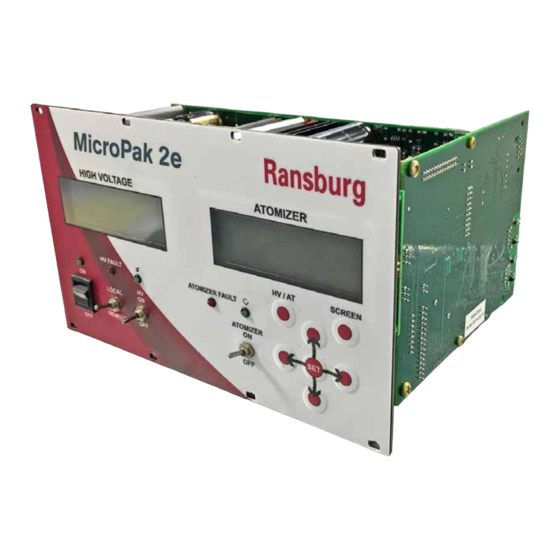
HV Controller - INTRODUCTION Return To Contents OPERATOR INTERFACE Ethernet/IP parameters. This means that when switching between Local and Remote modes, operating parameters will typically change. Parameters which always change are the ones passed as variables in the Ethernet/ The MicroPak 2e Controller shown in figure 4, has a IP Assemblies, e.g. -
Page 15: Buttons
HV Controller - INTRODUCTION Return To Contents So when the High Voltage is the active display, it will look High Voltage LED like “Figure 3 - 2nd Password Screen” in the PASSWORD PROTECTION section. The green High Voltage LED displays the current state of the High Voltage Output. -
Page 16: Hv Controller - Installation
HV Controller - INSTALLATION Return To Contents HV Controller - INSTALLATION GENERAL INFORMATION LOCATION OF PRODUCT Install the controller assembly in a control cabinet that is protected from the possibility of any contact with water, WA R N I N G vapor or high humidity. -
Page 17: Ethernet Connections
J4 power leads. When separate control of the cascade power is not required, power to J4 † The Ransburg MicroPak 2e Controller has a built and J11 can be run from one DC power supply. -
Page 18: Output To Cascade
HV Controller - INSTALLATION Return To Contents OUTPUT TO CASCADE TABLE 4 Cascades: HP404, RP404, HP505, Make connections from either J6 or J7 of the controller, RP1000, LEPS5002 depending on the cascade in use. Refer to Table 3 for J6 HVGND Pin 1 0 VDC for VCT Power connections and Table 4 for J7 connections. - Page 19 HV Controller - INSTALLATION Return To Contents 3. The low voltage cable has a large amount of high or power supply common. This adds large amounts of frequency noise on the shields and grounds from noise to these low voltage signals. To combat these being in proximity to the high voltage generator.
- Page 20 HV Controller - INSTALLATION Return To Contents Figure 11: MicroPak 2e Controller W/LEPS5002 or 74793 Cascade (RansPak 1000) Figure 12: MicroPak 2e Controller W/CONSOLIDATED Cascade LN-9624-00-R3 (05/2018) 20 / 74 www.carlisleft.com...
- Page 21 HV Controller - INSTALLATION Return To Contents Figure 13: Proper Power Supply and Grounding Connections LN-9624-00-R3 (05/2018) 21 / 74 www.carlisleft.com...
-
Page 22: Interlock Connections
HV Controller - INSTALLATION Return To Contents INTERLOCK CONNECTIONS Table 5 shows the pin assignments for the interlock signals. TABLE 5 - J5 CONNECTOR SIGNALS Outputs External Power Enable Pin 1, 2 System Alarm Out Pin 3, 4 Interlock Out Pin 5, 6 Interlock Inputs Door Interlock (+) -
Page 23: Hv Controller - Operation
HV Controller - OPERATION Return To Contents HV Controller - OPERATION START-UP SOFTWARE MISMATCH FAULT Before its’ first use, the following application specific The Micropak 2e family of products incorporate multiple features of the MicroPak 2e controller must be configured smart boards. -
Page 24: Start-Up Menu
HV Controller - OPERATION Return To Contents HIGH VOLTAGE NOTE DCP SW Ver: 1.1.15 † If the front panel Local/Remote Switch is in the “Remote” position, this screen will only be displayed HVC SW Ver: 1.1.15 for two seconds before the system automatically MIO SW Ver: 1.1.15 goes to Run Mode and changes the screen. -
Page 25: Menus And Operation
HV Controller - OPERATION Return To Contents The status is displayed via upper or lower case letters When a numeric value is being changed, a value change which indicate the associated board is communicating menu, similar to the one shown in Figure 17, will be displayed. (upper case) or not communicating (lower case). -
Page 26: Run Menus
HV Controller - OPERATION Return To Contents ATOMIZER HIGH VOLTAGE Value = DiDt Mode Dis Max UA Limit Range O to - Null O Save Quit Save_Changes Digit Mode Figure 19: Digit Mode Change Screen Figure 21: Voltage Mode Screen RUN MENUS The menu in Fig 22 is only displayed in Current Control Mode. -
Page 27: Configuration Menus
HV Controller - OPERATION Return To Contents Software Versions Menu ATOMIZER Starting with V1.1.07, an additional HIGH VOLTAGE menu has been added that displays the software versions ATf:RansNet CommLost of each board present in the system. It is the next screen HVflt:HV Power Off displayed if the user presses the “screen”... - Page 28 HV Controller - OPERATION Return To Contents Interlock Menu NOTE The three Interlock inputs which can be enabled or disabled are configured in this screen. As seen in Figure 28, the † The system DEFAULTS to have all interlocks first input is dedicated to use as an interlock and is labeled ENABLED.
- Page 29 HV Controller - OPERATION Return To Contents The configuration options that have been set for your applied. This is normally set as direct for all cascades except the RP1000 when used with an indirect charge ring, system at the factory will dictate the MP2e Remote Options The V-I limiting function is always enabled.
- Page 30 HV Controller - OPERATION Return To Contents response. In addition, when DHCP is enabled, an Ethernet/ Date Menu IP controller can configure the MicroPak 2e to save the This menu allows the user to set the date and time for the current configuration and use it at the next power cycle controller’s real-time clock (RTC).
-
Page 31: Configuration Parameters And Settings
HV Controller - OPERATION Return To Contents Broadcast Control Menu Date This parameter consists of the Month, Day and Year which This menu allows the user to control the filtering of excessive is maintained by the embedded real-time clock hardware. broadcast packets. -
Page 32: Diagnostics Menu
HV Controller - OPERATION Return To Contents Booth (Air) Note the INDIRECT type can only be selected when an RP1000 no cascade is configured. All other cascades will This parameter controls whether the MicroPak 2e Controller force Charge Type to be configured as DIRECT. will use the state of the Booth (Air) hardware input in its control calculations. -
Page 33: Operating Parameters And Settings
HV Controller - OPERATION Return To Contents The second screen, Figure 36 shows A2D (Analog to Digital) HIGH VOLTAGE readings for three of the system voltages along with the current system status. The items displayed are as follows: Keys=udlrcsaLoraE ATOMIZER PWR= 282O LGIC= 2685 1.8V= 2320 Figure 35: Diagnostic Key Screen... - Page 34 HV Controller - OPERATION Return To Contents di/dt Sensitivity HIGH VOLTAGE In Voltage Control Mode, this allows the user to control how rapid a current change can occur before a fault is KVSet V-CONSL generated. Allowable settings are 0 to 60, specified in KVAct uAAct units of µAmps per 100 milliseconds.
- Page 35 HV Controller - OPERATION Return To Contents dv/dt Sensitivity kV Low Limit In current control mode, this allows the user to control how This parameter determines the level where a kV Low Limit rapid a voltage change can occur before a fault is generated. Fault occurs.
-
Page 36: Control Conditions
HV Controller - OPERATION Return To Contents CONTROL CONDITIONS WARN System has detected a current or voltage condition within 10% of the limit settings. The abbreviation stands for Warning. Power Up On power up, the system does several checks to determine FALT hardware status. -
Page 37: Ethernet/Ip Interface
HV Controller - OPERATION Return To Contents SYSTEM FAULT BEHAVIOR Other HV Faults HV Action Atom Action Remote Stop Fault Disable The following tables specify how High Voltage or Atomizer Faults effect the operation of each other. HVC Power OFF Fault Disable System Mode... - Page 38 HV Controller - OPERATION Return To Contents Description of Interface Elements NOTE Input Word 0 † When an RP1000 or LEPS5002 cascade is selected, this value is multiplied by 5 to set the actual Bit 0 - Enable Control μA setpoint. When this bit is set (high) the system will attempt to keep the actual at the appropriate setpoint.
- Page 39 HV Controller - OPERATION Return To Contents TABLE 8 - MICROPAK 2e Ethernet/IP INPUT DEFINITIONS INPUT OBJECT (0X64) Word 0 Word 1 Word 2 Word 3 HV Enable Control kV Setpoint Parameter Value Reset Faults kV Setpoint Parameter Value Current Mode kV Setpoint Parameter Value kV Setpoint...
- Page 40 HV Controller - OPERATION Return To Contents Output Word 0 Bit 12 - Remote Stop (Interlock) Status This bit is set when the interlock was open when the HVC Fault occurred. Bit 0 - In Control This bit is set when control is enabled and the Bit 13 - Not in RUN STATE controlled value has reached within three of the This bit is set when the MP2e is not in RUN STATE.
- Page 41 HV Controller - OPERATION Return To Contents Bit 8 - Low Voltage Fault Bits (8-15) - Actual μA Value The system has fallen below the kV Limit Lo while This byte (8 bit) value displays the latest current in Current Mode. reading in μA.
- Page 42 HV Controller - OPERATION Return To Contents Parameter Select = 7: Password 1 READ - returns first character of user password WRITE - (Unsupported) Parameter Select = 8: Password 2 READ - returns second character of the password Parameter Select = 9: Password 3 READ - returns third character of user password WRITE - (Unsupported)
- Page 43 Atomizer Controller Atomizer Controller LN-9624-00-R3 (05/2018) 43 / 74 www.carlisleft.com...
-
Page 44: Atomizer Controller General Description
Atomizer Controller - INTRODUCTION Return To Contents Atomizer Controller - INTRODUCTION ATOMIZER CONTROLLER GENERAL DESCRIPTION The Atomizer Controller for use with the MicroPak 2e Controller is designed to continuously monitor and maintain the programmable speed of a rotary atomizer as well as provide a universal I/O interface for many atomizer functions. - Page 45 Atomizer Controller - INTRODUCTION Return To Contents SPECIFICATIONS (At Sea-Level Conditions) (Cont.) NOTE † Signals shown above in BOLD are minimum required functions for Atomizer control to operate. This note regarding the I/O names in BOLD also applies to the following descriptions. Electrical - Controls in Remote Ethernet/IP Mode Analog In:...
-
Page 46: Speed Control
Atomizer Controller - INTRODUCTION Return To Contents SPEED CONTROL An optional braking system provides for rapid slowdown. When changing speeds from high to low (change greater than 3,000 rpm), the controller provides an electrical brake The Atomizer Controller is used in a closed-loop rotational signal to drive a pneumatic solenoid which delivers high speed control system for rotary atomizers as shown in pressure air to the brake input of the... - Page 47 Atomizer Controller - INTRODUCTION Return To Contents The speed feedback signal is designed to drop out at about 2 krpm and the controller will set a Loss of Feedback Fault. A new speed command will reset the fault at the Atomizer Controller, but the MicroPak 2e Controller will only reset its fault indication when...
-
Page 48: Atomizer Controller - Operation
Atomizer Controller - OPERATION Return To Contents Atomizer Controller - OPERATION ATOMIZER OPERATION Atomizer MIO Dis The Atomizer Controller currently supports three different operating modes with varying levels of capabilities. Discrete MIO Dis Remote Ethernet/IP Control This mode gives the remote system full access to the atomizer parameters and allows control of starting and stopping as well as collection of fault information. -
Page 49: Cinfiguration Parameters And Settings
Atomizer Controller - OPERATION Return To Contents ATOMIZER WA R N I N G † ONLY USE the type of atomizer which the controller Discrete Analog Ins was configured for by the factory. Using a different V=O-1OV I=4-2OmA type atomizer may allow for operation outside the #1 V #2 V #3 V #4 V recommended parameters and values for the applicator and can result in damage or unsafe operation. -
Page 50: Automatic Shutdown
Atomizer Controller - OPERATION Return To Contents ShapeAirSP1 this interlock is to prevent fluid from being applied when it This parameter determines the level in percent (i.e. 0-100%) could easily flood the turbine. The second interlock prevents that will be applied to the Shaping Air 1 output. the solvent control output (i.e. -
Page 51: Interfacing Considerations
Atomizer Controller - OPERATION Return To Contents Low Bearing Air Pressure: Ethernet/IP INTERFACE If the bearing air pressure feedback drops below the minimum bearing air threshold. There is a 4 second time delay for all settings. The Ethernet/IP Interface for the Atomizer Controller is defined as two assembly instances that contain the MicroPak 6. - Page 52 Atomizer Controller - OPERATION Return To Contents TABLE 13 - ATOMIZER CONTROLLER Ethernet/IP INPUT BIT DEFINITIONS INPUT OBJECT (0X65) Word 4 Word 5 Word 6 Word 7 Word 8 Word 9 Atomizer ShapeAir 1 ShapeAir 2 Param Parameter Enable Setpoint Setpoint Setpoint Read Code...
- Page 53 Atomizer Controller - OPERATION Return To Contents Input Word 4 Bit 12 - Bell Cup Wash When this bit is set, the system will activate the Bell Cup Wash output and when cleared will de-activate Bit 0 - Atomizer Enable the Bell Cup Wash output.
- Page 54 Atomizer Controller - OPERATION Return To Contents Input Word 8 Bit 15 - Parameter Write Strobe When this bit changes from cleared to set, the Bits (0-6) - Parameter Read Code parameter value is written into the selected This 6 bit value determines the parameter to read. parameter and displayed in Output Word 7.
- Page 55 Atomizer Controller - OPERATION Return To Contents Bit 1 - Bell Underspeed Warning Output Word 4 This bit is set when the Atomizer detects Bit 0 - Bell Running an underspeed condition as described in the This bit is set when the atomizer control is enabled. “Automatic Shutdown”...
- Page 56 Atomizer Controller - OPERATION Return To Contents Bits (8-15) - Turbine Drive Value Parameter Select = 3: Input Mode This byte (8 bit) value displays the air pressure READ — returns bit values of 0-127 applied to the Atomizer turbine. If this value is WRITE —...
- Page 57 Atomizer Controller - OPERATION Return To Contents TABLE 17 NOTE † Current mode output requires the installation of an op- Digital Input tional 4-20 mA converter: Ransburg part number A13248-00. J5-1 1—Bell Spin Enable J5-3 2—Paint Trigger 1 † Location of the jumpers and I/O connectors referred to in tables 16, 17, 18 &...
-
Page 58: Discrete Io Controller General Description
Discrete IO Controller Discrete IO Controller LN-9624-00-R3 (05/2018) 58 / 74 www.carlisleft.com... -
Page 59: Discrete Io Controller - Introduction
Discrete IO Controller - INTRODUCTION Return To Contents Discrete IO Controller - INTRODUCTION DISCRETE IO CONTROLLER GENERAL DESCRIPTION The Discrete IO Controller, for use with the MicroPak 2e Controller, is designed to provide a universal I/O interface for high voltage controller functions. It is intended to be used in installations which do not support the standard MicroPak 2e Ethernet/IP control interface. -
Page 60: Configuration Parameters And Settings
Discrete IO Controller - INTRODUCTION Return To Contents SPECIFICATIONS (At Sea-Level Conditions) Electrical - Controls in Local Mode Analog In: (0-10V or 4-20mA) (None Active) Analog Out: (0-10V or 4-20mA with option) HV Output Level, Current Output Level Discrete In: (0-24V) (None Active) Discrete Out: (0-24V, Current Sourcing) HV Ready, HV On, Current Fault, dx/dt Fault, V/I Feedback Fault,... -
Page 61: Discrete Io Controller - Operation
Discrete IO Controller - OPERATION Return To Contents Discrete IO Controller - OPERATION Hardware Signals The Discrete IO Controller supports two operating modes. Remote Discrete Control TABLE 21 Remote control mode is activated when the front panel V-I Select Local/Remote switch is set to the Remote position. In Analog Inputs Jumper this mode, the Discrete IO controller’s inputs are used... -
Page 62: Discrete I/O Controller Logic Relating To Inputs On Connector J5
Discrete IO Controller - OPERATION Return To Contents DISCRETE I/O CONTROLLER TABLE 23 LOGIC RELATING TO INPUTS V-I Select Analog Outputs ON CONNECTOR J5 Jumper J4-1 1—HV Output Level JMP1 (Refer to signals in Table 22) J4-3 2—(Unassigned) JMP2 J4-5 3—(Unassigned) JMP3 Priority of inputs affecting the enabling of... -
Page 63: Micropak 2E Controls Integration Notes
INTEGRATION NOTES Return To Contents MicroPak 2e Controls - INTEGRATION NOTES GUIDELINES The MIO Discrete Outputs are implemented using IC drivers Controller DIP Switch Settings which source current from the 24VDC controller power. The Each of the MP2e boards have DIP switches. These are current draw on these outputs should not exceed 250 mA. - Page 64 INTEGRATION NOTES Return To Contents • Monitor the Ethernet/IP control network to confirm it CAUTION remains isolated. † Failure to interlock the flow of paint with atom- • If remote monitoring from the plant LAN is necessary, use izer rotation may cause damage to the atomizer. a managed gateway to limit access to the private LAN.
-
Page 65: High Voltage Controller Logic Relating To Inputs On Connector J5
INTEGRATION NOTES Return To Contents HIGH VOLTAGE CONTROLLER NOTE LOGIC RELATING TO INPUTS ON CONNECTOR J5 † Currently there is NO standard SBC configuration which routes this signal pair outside of the SBC (Interlocks and Remote signals) enclosure. † Currently there are 4 pairs of unassigned pins on Starting with software version V1.1.07, the High Voltage the SBC Interlock connector. -
Page 66: Maintenance
MAINTENANCE Return To Contents MAINTENANCE WA R N I N G † Before troubleshooting gun and control unit problems, flush the gun with solvent and purge with air. Some of the tests will require high voltage to be applied to the gun, so the gun must be empty of paint and solvent. - Page 67 MAINTENANCE Return To Contents TROUBLESHOOTING GUIDE - Fault / Warn (Cont.) General Problem Fault Report Explanation No Fault was detected. No Fault HVC Faults The current value has exceeded the I Limit Hi or the Max System Limit. Over Current The system has raised the Variable Voltage Output to the system MAX KV maximum, but could not reach the setpoint.
-
Page 68: Parts Identification
PARTS IDENTIFICATION Return To Contents PARTS IDENTIFICATION MICROPAK 2e HIGH VOLTAGE CONTROLLER - PARTS LIST Part No. Description A13338-XXXXXXXX MicroPak 2e HV & Atomizer Controller For replacement use, the user should order the same model number (-XXXXXXXX) listed on the original invoice. A13245-X1 MicroPak 2e Multi-Function Board, “X”... -
Page 69: Appendix
APPENDIX Return To Contents APPENDIX 8.160 (207.3mm) .139 (4.83mm) 4.540 (115.3mm) .112 Ø (2.84mm) #4-40 Tapped Hole .139 (4.83mm) .167 2.609 2.609 2.609 (4.24mm) (66.27mm) (66.27mm) (66.27mm) Figure 55: MicroPak 2e Controller Panel Mount Layout LN-9624-00-R3 (05/2018) 69 / 74 www.carlisleft.com... -
Page 70: Micropak 2E Controller/Multipfunction Io Layout
APPENDIX Return To Contents 4.7500 3.425 [87.00] 7.100 7.100 [180.34] [180.34] 3.675 [93.35] 4.350 [110.49] Figure 56: MicroPak 2e Controller/Multi-Function IO Layout LN-9624-00-R3 (05/2018) 70 / 74 www.carlisleft.com... -
Page 71: Initialization Screens
APPENDIX Return To Contents INITIALIZATION SCREENS ATOMIZER For Solventborne Aps On receipt from the factory, all MP2e units delivered with Software Version 1.1.00 and above will display the following a reasonable initial 11 initialization screens. These screens must be stepped Over Current Limit though and the requested parameters set before the MP2e will operate. -
Page 72: Appendix
APPENDIX Return To Contents ATOMIZER ATOMIZER Configure DiDt mode If Di/Dt is enabled and Sensitivity now: Di/Dt Sensitivity should be set to a DiDt Mode OO S non-zero value. Figure 66: Init Menu Screen 10 (Right) Figure 63: Init Menu Screen 7 (Right) Figure 66 above, allows the user to set the Di/Dt Mode and Di/Dt Sensitivity. -
Page 73: Manual Change Summary
MANUAL CHANGES Return To Contents MANUAL CHANGE SUMMARY LN-9624-00-R3 - Replaces LN-9624-00.2 with the folowing changes: Change Description Page(s) Update manual to new design All Pages Format Manual to show three contorollers; HV, Atomizer, and Discrete I/O All Pages Update “SPECIFICATIONS” 12-13 Change the range on the second screen (Figure 3), update figure numbers and add “User Password Menu”... - Page 74 This product is covered by Carlisle Fluid Technologies materials and workmanship limited warranty. The use of any parts or accessories, from a source other than Carlisle Fluid Technologies, will void all warranties. For specific warranty information please contact Carlisle Fluid Technologies.
Need help?
Do you have a question about the Ransburg MicroPak 2e and is the answer not in the manual?
Questions and answers