
Related Manuals for ESAB Aristo Robust Feed U6


Summary of Contents for ESAB Aristo Robust Feed U6
- Page 1 Aristo® Robust Feed U6, Robust Feed Pulse Instruction manual Valid for: serial no. 014-, 019-xxx-xxxx 0446 253 101 GB 20200629...
-
Page 3: Table Of Contents
External control panel................6.1.2 Internal control panel ................6.1.3 Function explanations ................Pulse ......................6.2.1 External control panel................6.2.2 Internal control panel ................Setting the gas flow ................Rotating the external control panel ............0446 253 101 © ESAB AB 2020... - Page 4 TABLE OF CONTENTS MAINTENANCE ................... Inspection and cleaning ................. TROUBLESHOOTING ................. ORDERING SPARE PARTS ................ DIAGRAM ......................ORDERING NUMBERS ..................40 WEAR PARTS ...................... ACCESSORIES ....................44 Rights reserved to alter specifications without notice. 0446 253 101 © ESAB AB 2020...
-
Page 5: Safety
Safety Data Sheets (SDSs). Safety precautions Users of ESAB equipment have the ultimate responsibility for ensuring that anyone who works on or near the equipment observes all the relevant safety precautions. Safety precautions must meet the requirements that apply to this type of equipment. The following recommendations should be observed in addition to the standard regulations that apply to the workplace. - Page 6 If equipped with ESAB cooler Use ESAB approved coolant only. Non-approved coolant might damage the equipment and jeopardize product safety. In case of such damage, all warranty undertakings from ESAB cease to apply. Recommended ESAB coolant ordering number: 0465 720 002.
- Page 7 There may be potential difficulties in ensuring electromagnetic compatibility of class A equipment in those locations, due to conducted as well as radiated disturbances. 0446 253 101 - 7 - © ESAB AB 2020...
- Page 8 For further information contact the nearest ESAB dealer. ESAB has an assortment of welding accessories and personal protection equipment for purchase. For ordering information contact your local ESAB dealer or visit us on our website. 0446 253 101 - 8 - ©...
-
Page 9: Introduction
The wire feed units are sealed and contain four-wheel drive wire feed mechanisms as well as control electronics. They can be used together with wire from ESAB's Marathon Pac™ or from wire bobbin (standard Ø 200 mm and Ø 300 mm). -
Page 10: Technical Data
-40 to +80 °C (-40 to +176 °F) Shielding gas All types intended for MIG/MAG welding Maximum gas pressure 5 bar (0.5 Mpa) ESAB's ready mixed coolant Coolant Maximum coolant pressure 5 bar (0.5 Mpa) Permissible load at +40 °C: 35% duty cycle... - Page 11 The IP code indicates the enclosure class, i.e. the degree of protection against penetration by solid objects or water. Equipment marked IP44 is intended for indoor and outdoor use and can withstand rain from all directions. 0446 253 101 - 11 - © ESAB AB 2020...
-
Page 12: Installation
Risk of crushing when lifting the wire feeder. Protect yourself and warn bystanders of the risk. CAUTION! To avoid personal injury and damage of equipment, lift using methods and attachment points presented below. 0446 253 101 - 12 - © ESAB AB 2020... - Page 13 The 44 kg / 97 lb. approved weight consists of wire feeder plus accessories (standard feeder weight is 18.5 kg / 40.8 lb., for all weights see the TECHNICAL DATA chapter). 0446 253 101 - 13 - © ESAB AB 2020...
-
Page 14: Operation
Before threading welding wire, make sure the chisel point and burrs have been removed from the end of the wire to prevent the wire from jamming in the torch liner. WARNING! Rotating parts can cause injury, take great care. 0446 253 101 - 14 - © ESAB AB 2020... -
Page 15: Recommended Maximum Current Values For Connection Cables Set
0.23 V / 100 A Duty cycle The duty cycle refers to the time as a percentage of a ten-minute period that you can weld or cut at a certain load without overloading. 0446 253 101 - 15 - © ESAB AB 2020... -
Page 16: Connections And Control Devices
Heat kit switch (Offshore variants) Connection for control cable from power source ELP = ESAB Logic Pump (see the "Cooling liquid connection" section) WARNING! The right and left side doors of the wire feed unit must be closed when welding and/or wire feeding occurs. -
Page 17: Cooling Liquid Connection
OFF position and the cooling unit switch must be in position 0. Some wire feed unit variants with cooling liquid connections included, are equipped with a detection system called ESAB Logic Pump (ELP) which checks that the water hoses are connected. When connecting a water-cooled welding torch, the water pump starts automatically. -
Page 18: Retrofit Of Interconnection Strain Relief Kit
5 OPERATION Retrofit of interconnection strain relief kit 0446 253 101 - 18 - © ESAB AB 2020... - Page 19 Locate the welding current cable in the larger of the two holes in the strain relief clamp! • Ensure that the cable ties around the insulating sleeve are tightened properly! 0446 253 101 - 19 - © ESAB AB 2020...
-
Page 20: Heat Kit Switch (Offshore Variants Only)
Do not overload the bobbin brake! A too high brake force may overload the motor and reduce the welding result. The bobbin brake force is adjusted using the 6 mm hexagon Allen screw in the middle of the spool nut. 0446 253 101 - 20 - © ESAB AB 2020... -
Page 21: Changing And Loading Wire
Remove the feed rollers and install the correct ones (according to the WEAR PARTS appendix). Reapply the pressure on the feed rollers, by pushing the swing arms (C) down and secure them using the tensioner units (B). 0446 253 101 - 21 - © ESAB AB 2020... -
Page 22: Changing The Wire Guides
Push in the correct type of wire guide (according to the WEAR PARTS appendix). The clip automatically locks the wire guide when in the correct position. 0446 253 101 - 22 - © ESAB AB 2020... -
Page 23: Outlet Wire Guide
A table showing approximate settings can also be found on the left side inside the wire feeder. 0446 253 101 - 23 - © ESAB AB 2020... -
Page 24: Wear Parts Storage Compartment
A wear parts storage compartment can be found on the inside of the left door of the wire feeder, for easy access to an extra set of rollers and wire guides. 0446 253 101 - 24 - © ESAB AB 2020... -
Page 25: Attachment Of Wheel Kit
Before the wire feed unit is attached to the wheel kit, fasten the wheels to the frame by means of the M12 screws, washers and nuts, using a tightening torque of 40 ±4 Nm (354 ±35.4 in. lb). The fixed wheels at the rear end should be positioned parallel to the frame. 0446 253 101 - 25 - © ESAB AB 2020... -
Page 26: Wire Feed Unit In Vertical Position
Wire feed unit in horizontal position NOTE! To be able to attach the wire feeder in horizontal position on the wheel kit, the two bumpers on the wire feeder door must be removed! 0446 253 101 - 26 - © ESAB AB 2020... -
Page 27: Attachment Of Both Wheel Kit And The Torch Strain Relief Accessory
If the torch strain relief accessory are to be used in connection to the wheel kit being attached in vertical position, the assembly has to be made in the following order: 0446 253 101 - 27 - © ESAB AB 2020... - Page 28 Fasten the wheel kit and the torch strain relief to the wire feeder, using the two screw joints closer to the front end of the wire feeder. 0446 253 101 - 28 - © ESAB AB 2020...
-
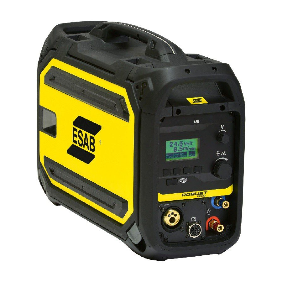
Page 29: Control Panel
Display Soft pushbuttons (function keys), see further explanation in the U6 control panel instruction manual Knob for setting the voltage Menu button Knob for setting the wire feed speed and current 0446 253 101 - 29 - © ESAB AB 2020... -
Page 30: Internal Control Panel
Local The local function enables the external control panel in the wire feeder and disables the remote control for Push Pull torch or Miggytrac/Railtrac options. 0446 253 101 - 30 - © ESAB AB 2020... -
Page 31: Pulse
Pulse control panel are shown in the display instruction manual Display Knob for setting the wire feed speed and current Knob for setting of voltage/QSet™ Indication of activated VRD (Voltage Reducing Device) 0446 253 101 - 31 - © ESAB AB 2020... -
Page 32: Internal Control Panel
Remove the two screws for the control panel and remove the panel. Rotate the control panel 90° counter-clockwise. Attach the control panel making sure the small tabs are in the correct position. Fasten the screws. 0446 253 101 - 32 - © ESAB AB 2020... - Page 33 6 CONTROL PANEL 0446 253 101 - 33 - © ESAB AB 2020...
-
Page 34: Maintenance
The wear parts of the welding torch should be cleaned and replaced at regular intervals in order to achieve trouble-free wire feed. Blow the wire guide clean regularly and clean the contact tip. 0446 253 101 - 34 - © ESAB AB 2020... -
Page 35: Troubleshooting
Fault symptom Corrective actions The wire feed is slow/stiff • Clean the liners and other mechanical parts of the wire through the wire feed feed mechanism, using pressurized air. mechanism. 0446 253 101 - 35 - © ESAB AB 2020... -
Page 36: Ordering Spare Parts
Spare parts and wear parts can be ordered through your nearest ESAB dealer, see esab.com. When ordering, please state product type, serial number, designation and spare part number in accordance with the spare parts list. -
Page 37: Diagram
DIAGRAM DIAGRAM Robust Feed U6/Pulse 0446 253 101 - 37 - © ESAB AB 2020... - Page 38 DIAGRAM Robust Feed U6/Pulse EURO Push Pull 0446 253 101 - 38 - © ESAB AB 2020...
- Page 39 DIAGRAM Robust Feed U6/Pulse Tweco Push Pull 0446 253 101 - 39 - © ESAB AB 2020...
-
Page 40: Ordering Numbers
MMA 0445 800 894 Robust Feed Pulse, Water With EURO connector, torch cooling system 0445 800 891 Robust Feed Pulse, Offshore, Water With EURO connector, torch cooling system, heater, gas flow meter and MMA 0446 253 101 - 40 - © ESAB AB 2020... - Page 41 Therefore they are replaced with * here. Make sure to use a manual with a serial number or software version that corresponds with the product, see the front page of the manual. Technical documentation is available on the Internet at: www.esab.com 0446 253 101 - 41 - © ESAB AB 2020...
-
Page 42: Wear Parts
0446 080 882 0.9–1.6 mm (2 mm) 0445 830 881 (Euro) 0445 830 884 (Tweco) Wire diameter 0.070–3/32 in. 0445 822 002 0446 080 883 1.8–2.4 mm (3 mm) 0445 830 882 (Euro) 0446 253 101 - 42 - © ESAB AB 2020... - Page 43 0445 850 051 0445 850 052 Inlet wire guide Middle wire guide Outlet wire guide 0445 830 886 (Tweco) 0445 822 001 0446 080 881 (2 mm) 0445 830 885 (Euro) 0446 253 101 - 43 - © ESAB AB 2020...
-
Page 44: Accessories
MMA: current and arc force TIG: current, pulse and background current 0459 491 882 Remote control unit M1 10Prog CAN Choice of one of 10 programs MIG/MAG: voltage deviation TIG: and MMA current deviation 0446 253 101 - 44 - © ESAB AB 2020... - Page 45 95 mm² liquid cooled, 82 ft (25 m) 0459 528 975 95 mm² liquid cooled, 114 ft 10 in (35 m) 0446 050 881 Interconnection strain relief kit (for update of cables without strain relief) 0446 253 101 - 45 - © ESAB AB 2020...
- Page 46 Equipment for mechanized welding 0459 990 645 Miggytrac™ B5001 Equipment for mechanized welding 0398 146 016 Railtrac™ B42V Equipment for mechanized welding 0459 990 644 Railtrac™ BV2000 Equipment for mechanized welding 0446 253 101 - 46 - © ESAB AB 2020...
- Page 47 ACCESSORIES 0446 253 101 - 47 - © ESAB AB 2020...
- Page 48 For contact information visit esab.com ESAB AB, Lindholmsallén 9, Box 8004, 402 77 Gothenburg, Sweden, Phone +46 (0) 31 50 90 00 http://manuals.esab.com...
Need help?
Do you have a question about the Aristo Robust Feed U6 and is the answer not in the manual?
Questions and answers