
Related Manuals for ESAB Aristotig255 AC/DC DTE 255


Summary of Contents for ESAB Aristotig255 AC/DC DTE 255
- Page 1 Aristotig 255 AC/DC DTE 255 Instruction manual 0457 784 201 GB 031110 Valid for serial no. 810− to 246−...
-
Page 2: Table Of Contents
1 DIRECTIVE ............2 SAFETY . -
Page 3: Directive
DIRECTIVE DECLARATION OF CONFORMITY ESAB Welding Equipment AB, S−695 81 Laxå, Sweden, gives its unreserved guarantee that welding power source DTE 255 from serial number complies with standard IEC/EN 60974−1, in accord- ance with the requirements of directive (73/23/EEC) and addendum (93/68/EEC) and with standard EN 50199 in accordance with the requirements of directive (89/336/EEC) and addendum (93/68/EEC). - Page 4 MALFUNCTION − Call for expert assistance in the event of malfunction. READ AND UNDERSTAND THE INSTRUCTION MANUAL BEFORE INSTALLING OR OPERATING. PROTECT YOURSELF AND OTHERS! ESAB can provide you with all necessary welding protection and accessories. WARNING! Read and understand the instruction manual before installing or operating.
-
Page 5: Introduction
TIG torch Note: Remove the TIG torch when using the MMA method. When TIG−welding, remove the electrode holder. ESAB’s accessories for the product can be found on page 19. Equipment DTE 255 is delivered with:... -
Page 6: Installation
DTE 255 Power factor at max. current, MMA 0.93 Efficiency at max. current, MMA 0.75 Mains voltage 400 V +/− 10% 3 phases Mains frequency 50 − 60 Hz Welding cable, sectional area 35 mm Fuse, slow−acting 16 A Mains cable, sectional area 4 x 2.5 mm Dimensions l x w x h 510 x 310 x 555 mm... -
Page 7: Location And Connection
Location and connection Place the welding power source so that the cooling air in− and outlets remain free. Connect the shielding gas (see fig. on page 7). Connect the TIG torch and the torch return cable, alternatively the welding and return cable of the electrode holder (see fig. -
Page 8: Remote Control Unit
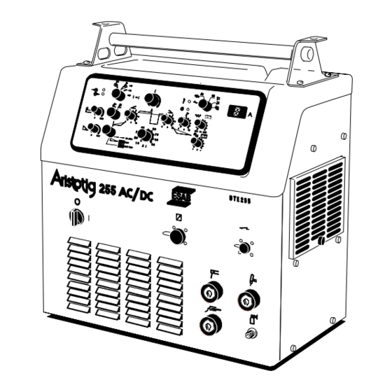
When the mains switching device is turned on, the diode (H) goes on. When open circuit voltage is applied diode (J) goes on. When an error occurs, for example overheating, diode (L) goes on. When there is no water flow diode (M) goes on. When there is a fault that can cause temporary high output voltage, the LED switches off (J), (output voltage has been switched off). - Page 9 Pulsing selection switch Non−pulsed welding, d.c. and a.c. Welding with square−wave pulsing; d.c. and a.c. Welding with trapezi−form pulsing; d.c. and a.c. Polarity selection switch Alternating current Square−wave alternating current Direct current, negative electrode (normal in TIG welding) Direct current, positive electrode Direct current, negative electrode, but with positive electrode at the start (for example for 3.2 mm electrodes, TIG welding).
- Page 10 Position = MMA In this position the welding power source is prepared for welding with coated electrodes. The HF unit and the Lift−Arc are disconnected, and the hot−start function is activated in order to supply incresaed current at the start. Position = HF unit ON When pressing the torch trigger the gas starts flowing, the HF unit goes on,...
-
Page 11: Mma Welding (Hand Welding Electrodes)
MMA welding (Hand welding electrodes) 6.5.1 Adjusting the control panel for MMA welding Connect the welding and return cable to the OKC terminals D and F. Set switch (1) to the position for hand welding electrodes. The LED (J) indicates that open circuit voltage is available on the welding terminals. -
Page 12: Tig Welding
TIG welding In TIG welding the torch trigger has three different functions: Two−stroke Four−stroke Four−stroke with the possibility to shift between two currents (shift function). 6.6.1 Adjusting the control panel for TIG welding Connect the TIG burner and the earth lead into the OKC outputs E and F, (for central connection: terminals P and F). - Page 13 6.6.2 Schematic pulsed welding sequence: 1. The gas preflow time is preset at 10 ms. 2. Hot start: The start current is preset at 100 A. The time is adjusted on the front panel: 20 − 500 ms. (For MMA welding: 200 − 2000 ms.) 3.
-
Page 14: Forced Disconnection
6.6.3 Setting direct and alternating current Direct current: Set switch (4) to the position for direct current with negative polarity. If pulsing has been selected: Set the pulse current value using potentiometer (8). Set the background current in per cent of the pulse current value using potentiometer (9). -
Page 15: Maintenance
Spare parts may be ordered through your nearest ESAB dealer, see the last page of this publication. − 15 −... -
Page 16: Diagram
Diagram − 16 − Edition 031110 dpb1e11a... -
Page 17: Ordering Number
DTE 255 Ordering number Ordering no. Denomination Type Notes 0301 035 880 Welding power source DTE 255 with central connection for the TIG torch 0301 035 881 Welding power source DTE 255 with OKC connection for the TIG torch 0457 784 990 Spare part list DTE 255 −... -
Page 18: Spare Parts List
DTE 255 Spare parts list Item Ordering no. Denomination 0301 028 001 Grill 0301 054 001 Filter 0441 819 001 Screw 0301 027 001 Grill 0301 053 001 Filter Edition 031110 − 18 − dpb1s... -
Page 19: Accessories
DTE 255 Accessories Trolley (with room for gas bottle) ... . 0301 100 880 Return cable ......0369 857 888 Foot control FS 002 . - Page 20 ESAB subsidiaries and representative offices Europe NORWAY Asia/Pacific Representative offices AS ESAB AUSTRIA BULGARIA CHINA Larvik ESAB Ges.m.b.H ESAB Representative Office Shanghai ESAB A/P Tel: +47 33 12 10 00 Vienna−Liesing Sofia Shanghai Fax: +47 33 11 52 03 Tel: +43 1 888 25 11...
Need help?
Do you have a question about the Aristotig255 AC/DC DTE 255 and is the answer not in the manual?
Questions and answers