
Related Manuals for ESAB Origo Arc 650c


Summary of Contents for ESAB Origo Arc 650c
- Page 1 Arc 410c Arc 650c Arc 810c ™ ™ ™ ™ Origo Service manual 0349 300 082 080623 Valid for serial no. 734, 749, 751- -xxx- -xxxx...
-
Page 2: Table Of Contents
READ THIS FIRST ..........................3 INTRODUCTION ............................. 4 Design structure of the power source ....................4 TECHNICAL DATA..........................5 WIRING DIAGRAM..........................6 Component description ........................6 OrigoArc 410c ............................7 OrigoArc 650c ............................8 OrigoArc 810c ............................9 DESCRIPTION OF OPERATION......................10 MMC module............................ - Page 3 Checking chopper block V0 ....................... 33 Overview test ............................. 35 Rectifier test ............................35 Checking of output stage........................35 Replacing of damaged transistors..................... 36 NOTES ..............................37...
-
Page 4: Read This First
READ THIS FIRST Maintenance and repair work should be performed by an experienced person, and electrical work only by a trained electrician. Use only recommended replacement parts. This service manual is intended for use by technicians with electrical/electronic training for help in connection with fault--tracing and repair. -
Page 5: Introduction
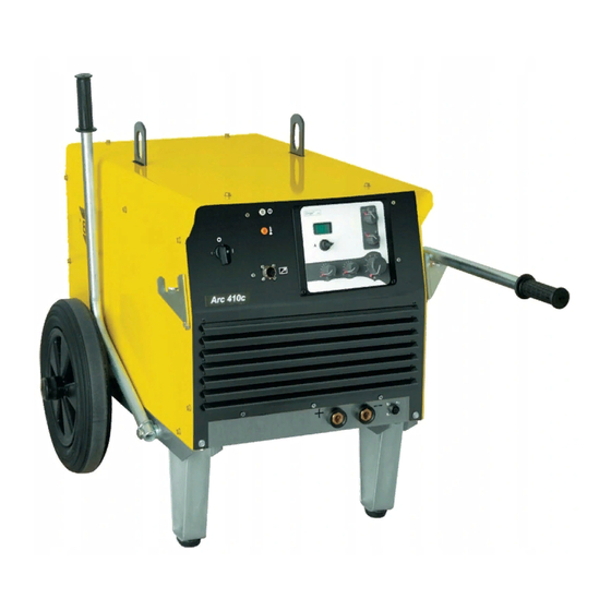
INTRODUCTION Origo Arc 410c, Arc 650c, Arc 810c, are chopper controlled welding rectifiers designed for welding with coated electrodes, TIG welding and arc air gouging. Origo Arc 650c and Arc 810c are delivered with panel A12. Origo Arc 410c may be delivered with panel A11 or A12. -
Page 7: Wiring Diagram
WIRING DIAGRAM WARNING ! STATIC ELECTRICITY can damage circuit boards and electronic components. Observe precautions for handling electrostatic- sensitive devices. Use proper static--proof bags and boxes. The power source consists of a number of function modules, which are described in the component descriptions on the following pages. -
Page 8: Origoarc 410C
Origo Arc 410c... -
Page 9: Origoarc 650C
Origo Arc 650c... -
Page 10: Origoarc 810C
Origo Arc 810c... -
Page 11: Description Of Operation
DESCRIPTION OF OPERATION This description of operation describes the function of circuit boards and other components in the power source. It is divided into sections, numbered to correspond to the circuit board numbers and divisions into function blocks. MMC module The MMC module consists of an operator’s control panel. -
Page 12: Control Panel A12
Control panel A12 Diagram of A12 Apart from potentiometers for current setting (R01), HOT START time (R02), ARC FORCE penetration depth (R03) and welding method switch (S1), A12 panel also consists of current setting location selection switch (S2), current and welding voltage meter and remote wireless current setting receiver. -
Page 13: Current And Welding Voltage Meter
Current and welding voltage meter The meter has been made on the basis of the application of the ICL7107 integrated circuit. S switch is used for selecting the measured quantity (current or voltage). If the switch is set to position “A”, negative voltage of –... -
Page 14: Remote Wireless Welding Current Setting Receiver Circuit
Remote wireless welding current setting receiver circuit Circuits D1 and D2 form an 8-bit meter recording the set value of welding current in binary numbers. A3 and A4 integrated circuits form the C/A converter which transforms the binary value of the current into the setting voltage of the value within the range of 0 –... -
Page 15: Lm11 Component Positions
LM11 Component positions... -
Page 16: Ch21 Control Circuit Board
CH21 Control circuit board Welding current setting circuit Reference voltage of 5.1V from the A2 integrated circuit is the source of the reference voltage for the setting circuit. In order to obtain the reference voltage required for setting the current – the 5.1V voltage is separated in the follower circuit consisting of the following elements: A13a, R .The R01 local setting potentiometer is connected in parallel to the C capacitor. -
Page 17: Antistic, Hotstart, Arc Force Functions
Switching to the remote wire supply mode is performed automatically after fixing the peripheral device to the X01 socket on the cap board of the device. The electronic system of remote setting is galvanically separated from the remaining electronic circuits controlling the source operation. The VC transoptor carries a signal which switches off the A17c key and switches on the A17d key, transmitting the signal from the A12b amplifier output onto the A13d separating follower input, thus... -
Page 18: Current Loop Control System
onto the non-inverting input of A14d comparator. In the AG mode, the ANTISTICK function is switched off by means of shorting the A14b comparator output with the activated output transistor of the A14a comparator. The HOT START function is carried out by A15 and D1 integrated circuits. When the welding starts and the arc ignition takes place, V transistor is switched on, which results in the high level on the A15a amplifier output. -
Page 19: Circuit Reducing The Current Required For Activating The Device
A voltage measurement signal proportional to the welding current is transmitted to the LM11/1 board located on the A12 panel via the RC filter composed of RA and CA elements. The welding voltage measurement signal is carried to the LM11/1 board via the filter composed of RV and CV elements. -
Page 20: Activation In Tig Method
Activation in TIG method After pressing the button on the torch, the current flow through the VC3 transoptor takes place. Switching on the transistor of the VC3 transoptor results in cutting the V transistor off and unblocking the PWM generator in the A2 integrated circuit. Switching on of the steering voltage via the V transistor switching on the K2 transmitter also takes place. -
Page 21: Power Transistors Control System (Driver)
Power transistors control system (driver) Controlling the PWM circuit driver is carried out via the VC5 transoptor, which controls the V transistor. The V transistor directly controls the complementary circuit made on V and V transistors which control the chopper transistor gates. The driver is supplied by positive voltage obtained from the rectifier on diodes V and V as well as by a negative voltage obtained from the... -
Page 22: Ch21 Component Positions
CH21 Component positions... -
Page 23: K69 Suppression Circuit Board
K69 Suppression circuit board Circuit diagram Component positions... -
Page 24: Remote Controls
REMOTE CONTROLS Remote control MMA1, MMA2, AT1, AT1 CoarseFine can be connected to the power sources. Wireless N02 can be connected to the power sources with A12 panel. Remote controls are described in a separate service manual with filename / ordering no. xxx. SERVICE INSTRUCTION WARNING ! STATIC ELECTRICITY can damage circuit... -
Page 25: Service Aid
Service aid We can offer a number of service tools that will simplify the service. Antistatic service kit Ordering no. 0740 511 001 The kit makes it easier to protect sensitve components from electrostatic discharge. Contents: A conductive mat (size 610 x 610 mm) A 1.5 metre long ground cable with a crocodile clip An adjustable wrist strap and cable with an inbuilt protective resistor... -
Page 26: Checking Supply And Reference Voltages
Checking supply and reference voltages Measure voltage in indicated points and check if they are within indicated ranges. -
Page 27: Calibrating The Remote Wire Current Setting Circuit
Calibrating the remote wire current setting circuit Switch the source to the MMA or ARC GOUGING mode and set the ARC FORCE and HOTSTART potentiometers to the minimum value. When the peripheral device of the remote current setting is disconnected, measure and record voltage in the measurement point 3 on the CH21 board in extreme positions of the local current setting potentiometer. -
Page 28: Calibrating Of The Source In Mma, Arc Gouging And Tig Mode
Calibrating of the source in MMA, ARC GOUGING and TIG mode Set the current setting to the minimum value. No-load state voltage of the source should equal 56V +/- 10%. Using the RP 5 assembly potentiometer set the load current for the output voltage of approx. -
Page 29: Checking The Antistick Function In Tig Mode
Unloading the source above the activating threshold should immediately result in achieving the welding current, i.e. 50A. Checking the ANTISTICK function in TIG mode Switch the source to TIG mode and set the welding current to the value of 50A. Switch on the source by shorting contacts in the X03 socket to the TIG torch connection. -
Page 30: Checking The Operation Of Pwm Driver
Checking the operation of PWM driver Oscillogram of voltage at pins 6 and 7 of the A2 circuit is presented in the drawing below: Checking the PWM signal PWM outputs oscillogram of the A2 circuit (measurement point 5) is presented in the drawing below: Checking the gate pulses Voltage oscillogram at the driver output for 100A load is presented in the drawing below:... -
Page 31: Checking Display Board Lm11
Checking display board LM11 Checking supply and reference voltages Measure voltages at shown test pins and check if their values lay within given limits. Current meter calibration Set the V/A switch located on the cap board to A position (current measurement) Set the S2 setting location switch to LOCAL position, and the S2 welding method switch to MMA or AIR GOUGING position. -
Page 32: Calibration Of The Current Value Set With The Remote Wireless Current Setting Receiver
LM11 CH21: Calibration of the current value set with the remote wireless current setting receiver. Set the S2 setting location switch to WIRELESS position Remove the ZW1 jumper located on the LM11 board and insert it into the ZW2. Using the R24 potentiometer set the value of 400A (for ORIGOArc 410c), 650A (for ORIGOArc 650c) and 800A (for ORIGOArc 810c). -
Page 33: Voltage Meter Calibration
Voltage meter calibration Set the V/A switch located on the cap board to the V position (voltage measurement) Connect the reference voltmeter to output terminals of the source Using the R12 potentiometer located on the LM11 board set the voltage indication for no- load voltage of the source according to the indication of the reference device... -
Page 34: Checking The Remote Current Setting Circuits
Checking the remote current setting circuits Checking the wire remote setting circuit Connect the peripheral device of the remote wire regulation to the X01 socket The source should switch to the wire remote setting mode automatically, regardless of the position of the S2 switch on the A12 panel. Check the possibility of regulating the set value within the whole current range (unloaded source) and the possibility of regulating the output current when the source is loaded. - Page 35 There are three types of chopper modules, each one for particular power source: 1. OrigoMig 4002c/4002cw 2. OrigoMig 5002c/5002cw 3. OrigoMig 6502c/6502cw Differences lay within heatsinks dimensions, type and number of power IGBT modules, capacitance of capacitors, type of rectifier diodes. All of types have similar structure. Assembled module view Views:...
-
Page 36: Overview Test
Overview test Each block consist of at least two serviceable parts. The first step of control is taking overview and checking if any parts are looking abnormal. Broken parts can have marks of thermal damage, change of colors or shape. If after that checking nothing was find out next step is electrical testing. Rectifier test The first part for test is input rectifier consisted of diodes and two heatsinks (details no 15). -
Page 37: Replacing Of Damaged Transistors
Replacing of damaged transistors. For replacing damaged transistor following parts have to disassembled: - diode rectifiers - output terminal - DC-link terminals unconnected from modules. Important note - IGBT module is symmetrical except two plastic pins for positioning PCB. During replacement check if “+”... -
Page 38: Notes
NOTES... - Page 40 ESAB subsidiaries and representative offices Europe NORWAY Asia/Pacific Representative offices AS ESAB AUSTRIA BULGARIA CHINA Larvik ESAB Ges.m.b.H ESAB Representative Office Shanghai ESAB A/P Tel: +47 33 12 10 00 Vienna- -Liesing Sofia Shanghai Fax: +47 33 11 52 03...
Need help?
Do you have a question about the Origo Arc 650c and is the answer not in the manual?
Questions and answers