Humanscale Float Installation Manual
Hide thumbs
Also See for Float:
- Assembly instructions manual (9 pages) ,
- Assembly instructions manual (36 pages) ,
- Disassembly instructions manual (15 pages)
Table of Contents
Advertisement
Quick Links
Installation Manual
Read all instructions carefully before installing this product or attempting to use it.
This product contains a loaded mechanism that is under tension. Do not attempt to remove
or alter any part of this product or in any way modify or tamper with any component of this
product other than as set forth in these instructions. Failure to comply with the instructions
provided may result in property damage or serious injury.
WARNING
1
Advertisement
Table of Contents

Related Manuals for Humanscale Float


Summary of Contents for Humanscale Float
- Page 1 Installation Manual WARNING Read all instructions carefully before installing this product or attempting to use it. This product contains a loaded mechanism that is under tension. Do not attempt to remove or alter any part of this product or in any way modify or tamper with any component of this product other than as set forth in these instructions.
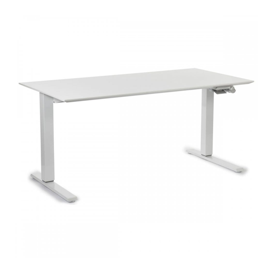
- Page 2 Parts List Left leg Cross-beam Release paddle Right leg Tension Indicator window Tension Adjustment screw Base Assembly ( Front view) Hardware Included (2) Feet (2) Wing Brackets (8) M8 × 30 mm button head screw (4) M6 × Tension Adjuster Handle Mounted Tension Adjuster Handle optional accessory *Work-surface not shown...
- Page 3 The work-surface must measure Front at least 3/4” (19 mm) thick. 2 ¼” (60 mm) Release Paddle positioning work-surface size 30” (800 mm) 16 ½” (420 mm) 24” (600 mm) 13 ½” (350 mm) Fig. M – Non Humanscale work-surface diagram.
- Page 4 Install the Mounted Tension Adjuster Handle Fig. H If you did not order your Float with this option, move on to Step 7 . Insert the hexagonal metal shaft of the Mounted Tension Adjuster Handle into the Tension Adjuster Screw on the front of the cross-beam.
- Page 5 If your Float is adjusted so that the Indicator Window is showing the needle at the 3/4 position or higher, and the Float Heavy Duty kit which can be installed to increase the weight capacity from 130 lbs. (60 kg) to 160 lbs. (70 kg).
Need help?
Do you have a question about the Float and is the answer not in the manual?
Questions and answers