
Related Manuals for Aetechron 7212


Summary of Contents for Aetechron 7212
- Page 1 7212 Operator’s Manual Four-Quadrant Power Amplifier for Power Utility Testing 574.295.9495 | www.aetechron.com 2507 Warren Street, Elkhart, IN 46516...
- Page 2 2507 Warren St. Elkhart, IN, 46516, U.S.A. receive an authorization to return the product for (574) 295-9495 service. All components must be shipped in a factory www.aetechron.c pack or equivalent which, if needed, may be obtained...
- Page 3 This Declaration of Conformity is issued under the sole responsibility of AE Techron, Inc., and belongs to the following product: Equipment Type: Industrial Power Amplifiers Model Name: 7212 EMC Standards: EN 61326-1: 2013 – Electrical Equipment for Measurement, Control and Laboratory use —...
-
Page 4: Table Of Contents
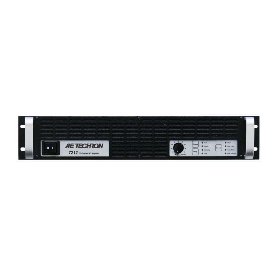
Contents 1 Introduction ............................6 1.1 Features ..........................6 2 Amplifier Unpacking and Installation ....................7 2.1 Safety First ..........................7 2.2 Unpacking ..........................7 2.3 Installation ..........................7 3 Connections and Startup .......................8 3.1 Other Operation Modes and Configurations................8 3.2 Connecting the Load ......................8 3.3 Connecting the Input Signal ....................9 3.4 Connecting the AC Supply ....................10 3.5 Start-up Procedure ......................10 4 ... - Page 5 List of Figures Figure 1.1 – 7212 Front Panel ......................6 Figure 3.1 – 7212 Back Panel ......................8 Figure 3.2 – Closeup of the Output Terminals ..................9 Figure 3.3 – Connecting the Load .......................9 Figure 3.4 – Closeup of SIM card ......................9 Figure 3.5 – Wiring and Internal Connections for BNC and Terminal Block Connectors .....9 Figure 3.6 – Closeup of AC Mains Outlet ..................10 Figure 3.7 – Sample of Configurations Setting Label ................10 Figure 4.1 – Power Switch.........................11 Figure 4.2 – Gain Control ........................11 Figure 4.3 – Push Buttons .........................11 Figure 4.4 – Indicators ........................12 Figure 4.5 – Main Status Indicators ....................12 Figure 4.6 – Fault Status Indicators....................13 Figure 4.7 – Back Panel Controls and Connectors ................14 Figure 5.1 – Access Panel Screw Locations ..................15 Figure 5.2 – Main Board Location Inside Access Panel ..............16 Figure 5.3 – Master/Follower Setting....................16 Figure 5.4 – Gain Trim Control ......................16 Figure 5.5 – Controlled-Voltage/Controlled-Current Mode Setting ............17 Figure 5.6 – Compensation Setting ....................17...
-
Page 6: Introduction
A single 7212 can output a 40 mSec pulse with up • System output of over 1,700 watts is possible to 30 amperes peak current. In continuous opera- with multiple, interconnected amplifiers tion, a 7212 can provide 440 watts RMS of output Efficient design and light-weight chassis • power. If more voltage is needed, up to four ampli- materials allow amplifier to occupy only 2U fiers can be combined in series and operate as a height and weigh only 35 lbs single system. -
Page 7: Amplifier Unpacking And Installation
7212 OPERATOR’S MANUAL – SECTION 2 2 Amplifier Unpacking and Along with any additional accessories purchased by the customer, all 7212 amplifiers ship with the Installation following: The 7212 amplifier is a precision instrument that • 7212 Amplifier can be dangerous if not handled properly. Lethal Toolkit (contains one #2 Phillips screwdriver • voltages are present in both the AC input supply and four rubber feet) and the outputs of this amplifier. For this reason, • Power Cord safety should be your primary concern when you 7212 Operator’s Manual USB drive and Quick • setup and operate this amplifier. Start sheet 2.1 Safety First 2.3 Installation Throughout this manual special emphasis is ... -
Page 8: Connections And Startup
7212 OPERATOR’S MANUAL – SECTION 3 Figure 3.1 – 7212 Back Panel 3 Connections and Startup This section details the wiring and startup pro- first be wired and tested individually in Controlled- cedures for a single 7212 amplifier operating in Voltage mode to ensure proper operation. Controlled-Voltage mode (factory default). Before To configure two or more amplifiers for Series or connecting the amplifier, make sure the AC power Parallel operation in Controlled-Voltage mode, refer cord is unplugged. to the Multi-Amp Configuration Guide (available for download from aetechron.com). WARNING For Series or Parallel operation in Controlled-Volt- ELECTRIC SHOCK HAZARD. age mode, refer to the “Applications” section of Output potentials can be lethal. -
Page 9: Connecting The Input Signal
7212 OPERATOR’S MANUAL – SECTION 3 Figure 3.2 – Closeup of the Output Terminals ply, signal source, or other inappropriate load; fire Figure 3.3 – Connecting the Load can result. NOTE: The 7212 amplifier comes with a factory-in- tors (BNC and three-pin terminal block), an Input Select switch, and a 37-pin Interlock – I/O Connec- stalled 2.7-ohm, 2W, 5%, metal-oxide resistor con- necting the terminals marked “COM and “CHAS- tor. Please refer to the Applications section for SIS GROUND” (see Figure 3.2). This resistor information on using the Interlock – I/O Connector. should NOT be removed. WARNING: Removing Connect from your signal source using either the this resistor can cause dangerous output and/ BNC jack or the three-pin terminal block connector. -
Page 10: Connecting The Ac Supply
7212 OPERATOR’S MANUAL – SECTION 3 Review the factory-set supply voltage and ampli- Hum occur when using the BNC Input, move fier configuration detailed on the label placed on the Input Select switch to the right to lift the the side of the amplifier (see Figure 3.7). This ground on the connector. configuration can be changed by the user. See the Connect using cables that are high quality and Advanced Configuration section for more infor- shielded to minimize noise and to guard against mation. possible feedback. -
Page 11: Amplifier Operation
7212 OPERATOR’S MANUAL – SECTION 4 4 Amplifier Operation 4.1.3 Push Buttons 4.1 Front-Panel Controls This section provides an overview of Front-Panel There are three Push Buttons on the 7212. controls and indicators found on the 7212. Enable – For stand-alone amplifiers, Enable will 4.1.1 Power Switch release the amplifier from Stop mode and place ... -
Page 12: Front-Panel Indicators
7212 OPERATOR’S MANUAL – SECTION 4 Reset – For stand-alone amplifiers, when a fault condition occurs, the amplifier may be placed in Standby mode (Standby LED will be lit), depending on the amplifier configuration and the fault condi- tion. To release the amplifier from Standby mode, clear the fault condition and then press the Reset button. If the amplifier is in Run mode when the fault condition occurs, pressing the Reset button Figure 4.4 – Indicators will return the amplifier to Run mode. If the amplifi- er is in Stop mode when the fault condition occurs, 4.2 Front-Panel Indicators pressing the Reset button will return the amplifier 4.2.1 Main Status Indicators to Stop mode. -
Page 13: Figure 4.6 - Fault Status Indicators
7212 OPERATOR’S MANUAL – SECTION 4 4.2.2 Fault Status Indicators fer to the chart in Figure 4.6 to determine the fault Four Fault Status indicators are located on the condition being indicated and the action required amplifier front panel (see Figure 4.4). These LEDs monitor the internal conditions of the amplifier to clear the fault condition. and will illuminate when a fault condition occurs. -
Page 14: Back-Panel Controls And Connectors
7212 OPERATOR’S MANUAL – SECTION 4 Back-Panel Controls and Connectors RIGHT position, the terminal block input connector This section provides an overview of Back-Panel is balanced, and the BNC input connector’s ground controls and connectors found on the 7212. Please connection is lifted. If circulating currents/ground refer to Figure 4.7 for visual locations. loops/60-Hz Hum occur when using the BNC input, AC Supply – Standard 20 amp 3-pin IEC-type move the Input Select switch to the right to lift the ... -
Page 15: Advanced Configuration
3. Remove the Access Panel and set it aside. requiring mid-level amounts of both voltage and current. Your 7212 amplifier has been pre-configured to your specifications before shipping from the fac- tory. These initial settings are detailed on your 7212 Proof of Performance sheet and on a label located on the side of the amplifier. If you need to make changes to your amplifier’s Figure 5.1 – Access Panel Screw Locations configuration, please follow the instructions con- 5.2 Configuration Settings Located on tained in this chapter. the Main Board WARNING The following custom settings can be made via ... -
Page 16: Figure 5.2 - Main Board Location Inside Access Panel
7212 OPERATOR’S MANUAL – SECTION 5 Stop Mode/Run Mode setting for selection of • power-up state. Standby mode on Over Temp setting to trigger • Standby mode when amplifier senses an Over- Temperature state. Standby mode on Over Load setting to trigger • Standby mode when amplifier senses an Over Load state. Figure 5.2 – Main Board Location Inside Access Panel 5.2.1 Master/Follower Setting To enable the 7212 amplifier for use as a single amplifier or as the Master amplifier in a multi-ampli- fier system, set jumpers P1 and P2 in the Master position (jumpers across top two pins of each set). ... -
Page 17: Figure 5.5 - Controlled-Voltage/Controlled-Current Mode Setting
5.2.3 Controlled-Voltage/ Controlled-Current Mode Setting To allow the 7212 amplifier’s output voltage to be controlled by its input voltage signal, place jumper J4 in the Right position. To allow the 7212 ampli- fier’s output current to be controlled by its input voltage signal, place jumper J4 in the Left posi- tion. See Figure 5.5. For more information on Figure 5.5 – Controlled-Voltage/ Controlled-Current operation, see the “Applica- Controlled-Current Mode Setting tions”... -
Page 18: Configuration Settings Located On The Power Supply Board
7212 OPERATOR’S MANUAL – SECTION 5 5.2.6 Standby Mode on Over Load Setting When enabled, the 7212 amplifier will move into Standby mode when it senses an activation of the IOC (Input/Output Comparator) Distortion Alert circuit. The IOC Distortion Alert circuit continuously compares the input waveform to the output wave- form. When a distortion of more than 0.5% occurs, the IOC circuit will activate. The amplifier will re- main in Standby Mode until the Reset switch on the Figure 5.8 – Standby Mode on Over Load Setting... -
Page 19: Figure 5.10 - Location Of Amplifier High-Voltage Transformer Sockets
7212 OPERATOR’S MANUAL – SECTION 5 1. Locate the SIM Input Card on the right side of the rear panel of the amplifier. 2. Using a #2 Phillips screwdriver (provided), remove the 2 screws located at the edges of the SIM card. 3. Keeping the ribbon cable attached, remove the SIM card from the amplifier until it is completely clear from the card bay. 4. Locate Bi-Level Power Switch, S1, a black, three-position switch at the rear of the card Figure 5.10 – Location of Amplifier High-Voltage bay.(See Figure 5.13) Transformer Sockets 5. Move Black switch to desired setting. If neces- sary, use a pointed, non-metallic object (such as a pen) to help in moving the switch. a. ... -
Page 20: Applications
7212 OPERATOR’S MANUAL – SECTION 6 6 Applications AE Techron 7212 amplifiers come with a SIM-BNC 6.1 Remote Status and Control using input module that also contains a female, 25-pin the SIM Interlock I/O Connector D-Sub connector. This connector can be used The procedures outlined in this section assume to provide remote control and monitoring of the competence on the part of the reader in terms of amplifier. ... -
Page 21: Figure 6.3 - Remote Status And Reset Schematic
7212 OPERATOR’S MANUAL – SECTION 6 6.1.2 Remote Amplifier Status and Reset Use a male, 25-pin D-Sub connector and high- The SIM Interlock I/O Connector can be used to quality wire to build the circuit. Figure 6.3 sche- create a circuit to monitor remotely one or more matic details the circuit and components required amplifier conditions, including Run status, Over- temperature, Overload and Overvoltage. The cir- for all status and reset functions. cuit can also be constructed to allow remote reset of the amplifier when it is forced to Standby due to ... -
Page 22: Figure 6.4 - Remote Enable/Standby
7212 OPERATOR’S MANUAL – SECTION 6 Remote Signal of Run Condition Remote Signal of OverVoltage Condition Purpose: LED, when lit, signals Run state. Purpose: LED, when lit, signals Overvoltage condition. Method: Use a 6mA series resistor of 4.02K-ohm Method: Use a 6mA series resistor of 4.02K-ohm for LED or OPTO, tie Run (PIN 12) to –24V source for LED or OPTO, tie OverVoltage Out (PIN 24) to (PIN 13). –24V source (PIN 13). Signal Type: DC Signal Type: DC Level when Asserted: –24V Level when Asserted: –24V Level when Deasserted: 0V... -
Page 23: Figure 6.5 - Remote Voltage Monitoring
Level when Deasserted: 0V Note: Used for monitoring amplifier output voltage; driving Follower amplifiers in multi-amp systems. Figure 6.5 – Remote Voltage Monitoring Wired to amplifier output. Do not connect to any im- Remote Monitoring of Current Output Purpose: Use a voltage meter to monitor output current. Method: Connect a voltage meter to monitor the output current being produced by the ampli- fier. Connect across PIN 6 (I MON+) and PIN 10 (Sampled Common). See Figure 6.6. Signal Type: DC Level when Asserted: 7212/7224: 5A/V; /7796: 20A/V Level when Deasserted: 0V Figure 6.6 – Remote Current Monitoring Information subject to change 97-8003058_08-31-2020... -
Page 24: Controlled Current Operation
Alternate Method Purpose: Use a voltage meter to monitor output current when output is not balanced. Method: Connect a voltage meter to monitor the output current being produced by the ampli- fier. Connect across PIN 6 (IMON+) and PIN 19 (IMON-). See Figure 6.7. Signal Type: AC Level when Asserted: 7212/7224: 2.5A/V; 7548/7796: 10A/V Level when Deasserted: 0V CAUTION: To avoid ground loops, isolation from ground must be provided. Use of a differential probe is recommended. Figure 6.7 – Remote Current Monitoring, Alternate Method 6.2 Controlled Current Operation... -
Page 25: Figure 6.9 - Input To Output Comparison, Controlled-Current Operation
7212 OPERATOR’S MANUAL – SECTION 6 6.2.3 Controlling Compensation for CC Operation AE Techron 7212 amplifiers can be configured for either Controlled Voltage (CV) or Controlled Cur- rent (CC) mode of operation. When operating the amplifier in Controlled Voltage (CV) mode, com- pensation is not required. However, when operat- ing in Controlled Current (CC) mode, the amplifier load becomes an integral part of the system. In order to ensure system stability and to control Figure 6.9 – Input to Output Comparison, available bandwidth, compensation via an RC Controlled-Current Operation network is required for CC operation. The following steps will allow you to compensate your amplifier 6.2.2 Safety and Operation Consider- for operation in CC mode safely and effectively. - Page 26 7212 OPERATOR’S MANUAL – SECTION 6 STEP 2: Determine Required Compensation. the following table to determine the approximate When operating an amplifier in Controlled Cur- compensation capacitance (C) required based on rent mode, the load becomes an integral part of the system. In order to determine the required the inductance of your load: compensation for your load, begin by consulting Load Inductance (L) <200 µH <>200 µH – <1 mH >1 mH 0.001 µF 0.01 µF 0.1 µF Compensation Capacitance (CC) NOTE: Load Resistance (R) is assumed to be <5 ohms.
-
Page 27: Figure 6.11 - Custom Compensation Location
7212 OPERATOR’S MANUAL – SECTION 6 COMPENSATION FORMULAS: After installing the components, check to ensure To find the value for the resistor (Rc) in the RC that jumper J5 is correctly installed (see STEP 4), network: then power up the amplifier without signal input. Rc = 20,000 x 3.14 x L x BW To begin testing, input a square wave with a fre- quency of 100 Hz to 1 kHz, or a squared pulse at a where: low level (typically 0.25 to 2.0 volts). A limited-rise- Rc is compensation resistance in ohms. time, repetitive pulse of low duty cycle is preferred. -
Page 28: Multi-Amplifier Systems
7212 OPERATOR’S MANUAL – SECTION 6 After final adjustments have been made to the circuit, the final waveform for your planned appli- cation should be tested to confirm the amplifier’s compensation setting. NOTE: • If possible, use 1% metal film resistors. AE Techron discourages installation of potentiome- Figure 6.13 – Square Wave Showing a Decrease in R is Required ters in the resistor location of the compensation circuit because this can decrease stability and If the output current waveform is rounded, the may increase inductance. - Page 29 AE Techron website at www. The 7212/7224 BAL RES KIT also contains the aetechron.com. shunt required to defeat the amplifier’s external level control. 6.3.1 Accessory Recommendations by System Type Parallel Systems Series Systems 7212 Two in Series: 7212 Two in Parallel: (2) 7212/7224 BAL RES kits, (2) SIM-BNC-OPTOC input cards, (1) DB9M OPTOC cable (1) 7212/7224 2-AMP Parallel Wiring kit 7212 Three in Series: 7212 Three in Parallel: (3) SIM-BNC-OPTOC input cards, ...
- Page 30 7212 OPERATOR’S MANUAL – SECTION 6 In multi-amp systems that have been configured to 6.3.2 Multiamp System Operation start up in Stop mode, when an amplifier is pow- In multiamp systems, the Master amplifier controls ered on, the amplifier will be placed in Standby/ several operating functions for all amplifiers includ- Stop mode (Stop and Standby LEDs lit). When ed in the system, so Follower amplifiers are said the Enable button is pressed on each amplifier, to be “interlocked” with the Master amplifier. The that amplifier will be placed in Remote Standby functions controlled by the Master amplifer include mode (Ready and Standby LEDs lit) and remain input signal, operating status, mode of operation in Remote Standby mode until all amplifiers in the (controlled-voltage or controlled-current operation) system have been Enabled. The system will auto- and amplifier compensation. matically proceed to Run mode when all amplifiers Because the amplifiers in a multiamp system are in the system achieve Remote Standby mode.
-
Page 31: Figure 6.16 - Main Status Indicators For Multi-Amplifier Systems
7212 OPERATOR’S MANUAL – SECTION 6 Main Status Indicators for Multi-amplifier Systems The Main Status indicators on each amplifier in system, the Main Status indicators can be used to determine the system status and the action a multi-amp system are used to determine the required to return the system to Run mode. See operational status of the amplifier. When evaluated along with the statuses of other amplifiers in the Figure 6.16. Figure 6.16 – Main Status Indicators for Multi-Amplifier Systems... -
Page 32: Figure 6.17 - Fault Status Indicators For Multi-Amplifier Systems
7212 OPERATOR’S MANUAL – SECTION 6 Fault Status Indicators for Multi-Amp Systems The four Fault Status indicators located on each cally, the system can be released from Standby amplifier’s front panel are used to monitor the mode by pressing the Reset button on the ampli- internal conditions of the amplifier and will illumi- fier displaying the Fault status. Refer to the chart in nate when a fault condition occurs. All amplifiers in Figure 6.16 to determine the fault condition being indicated and the action required to clear the fault the system may be placed in Standby mode when a fault condition occurs, depending on the fault ... - Page 33 7212 OPERATOR’S MANUAL – SECTION 6 One or More Amps in System Other Amps in System Action Needed to Clear Fault Main Status Fault Status Main Status Fault Status Condition and Re- Indicators Indicators Indicators Indicators State of Operation turn to Run Mode Over Temp status: To reset after an Over Each amplifier in the ...
- Page 34 7212 OPERATOR’S MANUAL – SECTION 6 6.3.3 Multi-Amp System Output Capabilities Two 7212s in Series – High-Voltage Mode PEAK OUTPUT RMS OUTPUT 1 Hour, 1 Hour, 40 mSec Pulse, 5 Minutes, 5 Minutes, 20% Duty Cycle 100% Duty Cycle 100% Duty Cycle 100% Duty Cycle 100% Duty Cycle Ohms Volts Amps Volts Amps Volts Amps Volts...
- Page 35 7212 OPERATOR’S MANUAL – SECTION 6 Three 7212s in Series – High-Current Mode PEAK OUTPUT RMS OUTPUT 1 Hour, 1 Hour, 40 mSec Pulse, 5 Minutes, 5 Minutes, 20% Duty Cycle 100% Duty Cycle 100% Duty Cycle 100% Duty Cycle 100% Duty Cycle Ohms Volts Amps Volts Amps Volts Amps Volts Amps Volts Amps Watts 14.9 14.9...
- Page 36 7212 OPERATOR’S MANUAL – SECTION 6 Two Paralleled 7212s – High-Voltage Mode PEAK OUTPUT RMS OUTPUT 1 Hour, 1 Hour, 40 mSec Pulse, 5 Minutes, 5 Minutes, 20% Duty Cycle 100% Duty Cycle 100% Duty Cycle 100% Duty Cycle 100% Duty Cycle Ohms Volts Amps Volts Amps Volts Amps Volts Amps Volts Amps Watts 10.2 14.8 12.6...
- Page 37 7212 OPERATOR’S MANUAL – SECTION 6 Three Paralleled 7212s – High-Current Mode PEAK OUTPUT RMS OUTPUT 1 Hour, 1 Hour, 40 mSec Pulse, 5 Minutes, 5 Minutes, 20% Duty Cycle 100% Duty Cycle 100% Duty Cycle 100% Duty Cycle 100% Duty Cycle Ohms Volts Amps Volts Amps Volts Amps Volts Amps Volts Amps Watts 0.67 44.7 44.7...
-
Page 38: Amplifier Signal Flow
7212 OPERATOR’S MANUAL – SECTION 7 7 Amplifier Signal Flow 7.2 AC Mains Power Power to the amplifier is connected through a 20- 7.1 Input Signals amp IEC-type inlet connector with an integral EMI The input signal is routed from the SIM (Specialized filter network on the back panel. AC mains power is Input Module) on the back panel to the Main board. first routed through the front panel switch/breaker, From there, the signal is amplified through low-noise then to the Power Supply board. From there, the AC operational amplifier gain stages, compensation mains are distributed to the main power transform- networks, and current limiting/ODEP and then final ... -
Page 39: Maintenance
7212 OPERATOR’S MANUAL – SECTION 8 8.1 Clean Amplifier Filter and Grills 8 Maintenance 8.1.1 Tools Required Simple maintenance can be performed by the user The recommended equipment and supplies to help keep the equipment operational. The fol- needed to perform the functions required for this lowing routine maintenance is designed to prevent task are described below. problems before they occur. See Section 8, Trou- bleshooting, for recommendations for restoring the • Vacuum cleaner equipment to operation after an error condition has ... -
Page 40: Troubleshooting
7212 OPERATOR’S MANUAL – SECTION 9 9 Troubleshooting 9.2 Visual Inspection Before attempting to troubleshoot the amplifier 9.1 Introduction & Precautions while it is operating, please take time to complete This section provides a set of procedures for a visual inspection of the internal components of identifying and correcting problems with the 7212 the amplifier. amplifier. Rather than providing an exhaustive and 1. To perform a Visual Inspection, first turn the detailed list of troubleshooting specifications, this Breaker/Switch to the Off (O) position. section aims to provide a set of shortcuts intended 2. -
Page 41: No Signal
7212 OPERATOR’S MANUAL – SECTION 9 please return it to AE Techron or an AE Techron Service Center for repair. 9.3 No Signal Missing Output signal may be caused by one of the following: 1. Master/Follower Jumpers are set to the Follower (down) position. The amplifier should only be configured for Follower mode if it is in a multi- amplifier system; otherwise it should be set for Master mode. See the “Advanced Configura- tion” section in this manual for more informa- tion. -
Page 42: Amplifier Overheats (Over Temp Fault Condition)
9.7 Amplifier Overheats (Over Temp to run for five minutes, and then push and hold Fault Condition) the Reset button until the Standby LED turns off to There are two possible reasons why the 7212 am- reset the amplifier. plifier is overheating: 1. Excessive Power Requirements 9.8 Fault LED is Illuminated 2. Inadequate Airflow The 7212 contains protection circuitry that disables 9.7.1 Excessive Power Requirements the amplifier if an output stage is behaving abnor-... - Page 43 7212 OPERATOR’S MANUAL – SECTION 9 Return Authorizations can be requested on our Please send all service units to the following ad- website or by contacting our Customer Service dress and be sure to include your Return Authori- Department. zation Number on the box. AE Techron, Inc. Please take extra care when packaging your am- Attn: Service Department / RMA# plifier for repair. It should be returned in its original 2507 Warren Street packaging or a suitable alternative. Replacement Elkhart, IN 46516 packaging materials can be purchased for a nomi- nal fee. Information subject to change...
-
Page 44: Specifications
7212 OPERATOR’S MANUAL – SECTION 10 10 Specifications Performance AC testing was performed at 1 kHz. Front Panel LED Displays indicate: Ready, Standby, Fault, Over Temp, Over Voltage, Frequency Response, DC - 100 kHz (1 watt): Overload +0.0 to -3.0 dB Soft Touch Switches for: 8-Ohm Power Response: Enable, Stop, Reset DC to 60 kHz: ±140 Vpk DC to 100 kHz: ±50 Vpk Gain Control, when enabled: Voltage gain adjustable from 20 to 0 ... -
Page 45: Figure 10.1 - Voltage Potential Vs. Frequency
Breaker protection on both main power and low volt- age supplies Protection Over Temperature: Over/Under Voltage: Separate Output transistor, heat sink, and transform- ± 10% from specified supply voltage amplifier is er temperature monitoring and protection forced to Standby 7212 AC Specifications – High-Voltage Mode PEAK OUTPUT RMS OUTPUT 1 Hour, 1 Hour, 40 mSec Pulse, 5 Minutes, 5 Minutes, 20% Duty Cycle... - Page 46 0V (not ready) to -15V (ready), with an OPTOC BNC card the signal will go from 0V (not ready) to -1.2Vdc (ready) I MON + Differential Current Current Monitoring: Connect a voltage meter to mon- AC or 7212/7224/ Output current produced per volt- Monitor + age detect. itor the output current being produced by the amplifier. 7226: 5A/V 7548/7794/ For unbalanced, for each 1V detected, current output is 5A (7212/7224/7226) or 20A (7548/7794/7796/7796HC). 7796/7796HC: 20A/V...
- Page 47 Standby of all amps in a multi-amplifier system. Input Monitor (OEM Used to monitor the input signal OEM modification only; normally no connection. OEM App only) from an OEM DAC card; this is the actual input signal. I MON – Differential Current Inverted I MON+ (PIN 6). Output Current Monitoring: Connect a voltage meter to AC or 7212/7224/ (alt.: OEM Monitor – ; 7226: 5A/V current produced per voltage monitor the output current being produced by the App) (- Input Monitor, amplifier. For each 1V detected, current output is 5A 7548/7794/ detect. OEM only) (7212/7224/7226) or 20A (7548/7794/7796/7796HC). 7796/7796HC:...
- Page 48 Pin # Function Description Signal Level when Level when Notes Applications Type Asserted Deasserted I SUM1– Multiple Amplifier Planned for use in multiple amplifier Currently not used. Summing, Ampli- configurations - paralleled and run- fier 1 ning Controlled Current Mode I SUM2– Multiple Amplifier Planned for use in multiple amplifier Currently not used. Summing, Ampli- configurations - paralleled and run- fier 2 ning Controlled Current Mode I SUM3– Multiple Amplifier Planned for use in multiple amplifier Currently not used. Summing, Ampli- configurations - paralleled and run- fier 3...
Need help?
Do you have a question about the 7212 and is the answer not in the manual?
Questions and answers