Sign In
Upload
Download
Table of Contents
Contents
Add to my manuals
Delete from my manuals
Share
URL of this page:
HTML Link:
Bookmark this page
Add
Manual will be automatically added to "My Manuals"
Print this page
×
Bookmark added
×
Added to my manuals
Manuals
Brands
Aetechron Manuals
Amplifier
7794
Operator's manual
Aetechron 7794 Operator's Manual
Single-channel industrial amplifiers for demanding, high-power systems
Hide thumbs
1
2
3
4
5
6
Table Of Contents
7
8
9
10
11
12
13
14
15
16
17
18
19
20
21
22
23
24
25
26
27
28
29
30
31
32
33
34
35
36
37
38
39
40
page
of
40
Go
/
40
Contents
Table of Contents
Troubleshooting
Bookmarks
Table of Contents
Declaration of Conformity
Table of Contents
1 Introduction
Features
Figure 1.1 - 7548 Front Panel
2 Amplifier Setup
Safety First
Unpacking
Installation
Connecting the Load
Figure 2.1 - Connecting the Load
Figure 2.2 - Close-Up of the Output Terminal Resistor
Connecting the Input Signal
Figure 2.3 - Close-Up of SIM Card
Figure 2.4 - Wiring for Unbalanced or Balanced Input Connector
Connecting the AC Supply
Start-Up Procedure
Figure 2.5 - 208V 3-Phase AC Mains Wiring
Figure 2.6 - 380/400/415V 3-Phase AC Mains Wiring
3 Amplifier Operation
Front-Panel Controls & Display
Figure 3.1 - Front Panel Controls and Display
Input Buttons
Front-Panel Indicators
Figure 3.2 - Front Panel Indicators
Figure 3.3 - Main Status Indicators for Stand-Alone Amplifiers
Navigation Buttons
Figure 3.4 - Fault Status Indicators for Stand-Alone Amplifiers
Figure 3.5 - Main Status Indicators for Multi-Amplifier Systems
Figure 3.6 - Fault Status Indicators for Multi-Amplifier Systems
Back-Panel Controls and Connectors
Figure 3.7 - Back Panel Controls and Connectors
4 Advanced Configuration
Factory Defaults
Accessing the Main Board
Configuration Settings Located on the Main Board
Figure 4.1 - Master or Slave Setting
Figure 4.2 - Gain Trim Control
Figure 4.3 - Controlled-Voltage or Controlled-Current Mode Setting
Figure 4.4 - Compensation Setting
Figure 4.5 - Ready/Run Mode or Standby Mode on Power-Up Setting
Figure 4.6 - Standby Mode on Overtemp Setting
Figure 4.7 - Standby Mode on Overload Setting
Adjusting the Bi-Level Power Supply Switch
Figure 4.8 - Bi-Level Power Switch Location
5 Applications
Remote Status and Control Using the SIM Interlock I/O Connector
Figure 5.1 - Remote Status and Control Pinouts
Figure 5.2 - Remote Run/Standby Monitor
Figure 5.3 - Remote Status and Reset Schematic
Figure 5.4 - Remote Enable/Standby
Figure 5.5 - Remote Voltage Monitoring
Figure 5.6 - Remote Current Monitoring
Controlled Current Operation
Figure 5.7 - Remote Current Monitoring, Alternate Method
Figure 5.8 - Input to Output Comparison, Controlled-Voltage Operation
Figure 5.9 - Input to Output Comparison, Controlled-Current Operation
Figure 5.10 - Factory-Installed Default RC Network
Figure 5.11 - Custom Compensation Location
Figure 5.12 - Compensation Effects on Waveform
Multi-Amplifier Systems
Figure 5.13 - Square Wave Showing a Decrease in R Is Required
Figure 5.14 - Square Wave Showing an Increase in R Is Required
Figure 5.15 - Square Wave Showing an Increase in C Is Required
6 Maintenance
Clean Amplifier Filter and Grills
7 Troubleshooting
Introduction & Precautions
Visual Inspection
Figure 7.1 - +VCC and -VCC Point Locations
Figure 7.2 - Amplifier Cover Removed for Inspection
No Signal
No Leds Illuminated or no Fans
Overvoltage Warning Message
Standby LED Remains Illuminated
Figure 7.3 - Fuse F1 Location
Figure 7.4 - Interlock I/O Connector
Amplifier Overheats (over Temp Fault Condition)
Figure 7.5 - +TEMP and -TEMP Test Point Locations
Fault LED Is Illuminated
Factory Service
8 Specifications
Advertisement
Quick Links
Download this manual
7548/7794/7796
Operator's Manual
Single-Channel Industrial Amplifiers for Demanding, High-Power Systems
APPLIES TO UNITS WITH MAINBOARD PART NUMBER 65-7796135-3
574.295.9495 |
www.aetechron.com
2507 Warren Street, Elkhart, IN 46516
Table of
Contents
Previous
Page
Next
Page
1
2
3
4
5
Advertisement
Table of Contents
Need help?
Do you have a question about the 7794 and is the answer not in the manual?
Ask a question
Questions and answers
Related Manuals for Aetechron 7794
Amplifier Aetechron 7548 Operator's Manual
Single-channel industrial amplifiers for demanding, high-power systems (40 pages)
Amplifier Aetechron 7796 Operator's Manual
Single-channel industrial amplifiers for demanding, high-power systems (40 pages)
Amplifier Aetechron 7228 Operator's Manual
Single-channel industrial amplifier for demanding, high-power systems (55 pages)
Amplifier Aetechron 7114 Operating Manual
Precision industrial ac/dc amplifier (33 pages)
Amplifier Aetechron 7548RLY Operator's Manual Supplement
(5 pages)
Amplifier Aetechron 7548RLY Operator's Manual
(10 pages)
Amplifier Aetechron 7212 Operator's Manual
Four-quadrant power amplifier for power utility testing (48 pages)
Amplifier Aetechron 7234 Operator's Manual
Single-channel industrial amplifier for demanding, high-power systems (53 pages)
Amplifier Aetechron 7220 Series Operator's Manual
Single-channel industrial amplifiers (71 pages)
Amplifier Aetechron 7224 Operator's Manual
(88 pages)
Amplifier Aetechron 7224RLY Operator's Manual Supplement
Dc enabled ac amplifier (8 pages)
Amplifier Aetechron 2110 Operator's Manual
Gradient amplifiers (45 pages)
Amplifier Aetechron 2105 Operator's Manual
Gradient amplifier (37 pages)
Amplifier Aetechron 8704 Operator's Manual
(37 pages)
Amplifier Aetechron 8700 Series Operator's Manual
Ultra-wide-bandwidth, high-power switch-mode amplifiers (41 pages)
Amplifier Aetechron 9205 Operator's Manual
Wide-bandwidth, high-power, multi-channel digital amplifiers (24 pages)
Summarization of Contents
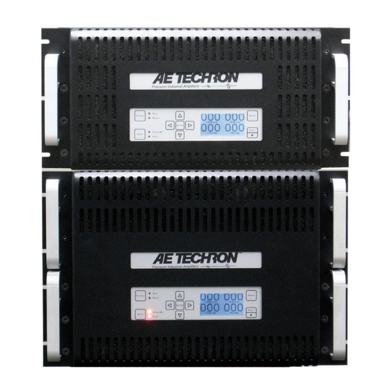
Introduction to AE Techron Amplifiers
Key Amplifier Features Overview
Details amplifier features like protection circuitry, cooling, and front-panel interface for demanding systems.
Amplifier Setup and Installation
Safety First and Precautions
Highlights essential safety precautions and symbols to ensure safe operation and handling.
Unpacking and Initial Inspection
Instructions for unpacking the amplifier, inspecting for damage, and retaining shipping materials.
Installation and Rack Mounting
Guidance on rack mounting, ensuring proper ventilation, and airflow requirements for the amplifier.
Connecting Load and Input Signals
Procedures for connecting the load to the output terminals and input signals via the SIM card.
AC Power Connection Procedure
Safe and correct procedures for connecting the amplifier to the 3-phase AC mains power supply.
Amplifier Start-up Procedure
Step-by-step guide for powering up the amplifier safely and verifying operational readiness.
Amplifier Operation and Controls
Front-Panel Controls and Display
Overview of front-panel buttons (Enable, Stop, Reset), LCD display, and navigation controls.
Front-Panel Status Indicators
Explanation of Main and Fault Status LEDs for indicating amplifier operational states and fault conditions.
Multi-Amplifier System Status
How status indicators reflect system status and actions in multi-amp configurations.
Back-Panel Controls and Connectors
Identification and description of back-panel connectors for power, signal input, and output.
Advanced Configuration Options
Factory Default Settings
Details the amplifier's default configuration settings for initial operation.
Accessing and Configuring the Main Board
Procedure for safely accessing the main board and overview of available custom settings.
Master/Slave Settings and Gain Trim
Configuring amplifier roles (master/slave) and adjusting gain using onboard controls.
Controlled Voltage/Current Mode Selection
Selecting between Voltage-Controlled Voltage Source (CV) and Current Source (CC) operational modes.
CC Mode Compensation and Power Supply
Setting up RC networks for CC mode stability and adjusting Bi-Level power supply modes.
Applications and System Integration
Remote Status and Control via Interlock
Using the interlock connector for remote monitoring of amplifier status and control functions.
Remote Voltage and Current Monitoring
Methods for remotely monitoring output voltage and current using the interlock connector.
Controlled Current Operation Guidelines
Safety, operation, and compensation guidelines for Controlled Current mode.
Multi-Amplifier System Integration
Configuring multiple amplifiers in series or parallel for enhanced voltage or current output.
Routine Maintenance Procedures
Cleaning Amplifier Filters and Grills
Instructions for cleaning air filters and grills to ensure proper cooling and maximum efficiency.
Required Tools for Maintenance
Lists the essential tools and supplies needed for performing cleaning and maintenance tasks.
Troubleshooting Amplifier Issues
Initial Troubleshooting and Visual Inspection
Procedures for initial diagnosis and visual inspection of internal components for faults.
Diagnosing Signal and Power Issues
Troubleshooting steps for common issues like no signal, no LEDs, and overvoltage warnings.
Resolving Over-Temperature and Fault Conditions
Identifying causes of overheating and fault LEDs, and procedures for resetting the amplifier.
Factory Service and Return Procedures
Information and steps for returning the amplifier for factory service or repair.
Amplifier Technical Specifications
Performance Specs (Controlled Voltage Mode)
Detailed electrical and performance metrics for the amplifier operating in CV mode.
Input Characteristics and Gain Specifications
Specifications related to input signal types, impedance, sensitivity, and gain parameters.
Front/Back Panel I/O and Controls Specs
Specifications for front and back panel components, connectors, and user interface elements.
Protection Features and Physical Attributes
Details on protection mechanisms, chassis construction, weight, and environmental operating limits.
Table of Contents
Print
Rename the bookmark
Delete bookmark?
Delete from my manuals?
Login
Sign In
OR
Sign in with Facebook
Sign in with Google
Upload manual
Upload from disk
Upload from URL
Need help?
Do you have a question about the 7794 and is the answer not in the manual?
Questions and answers