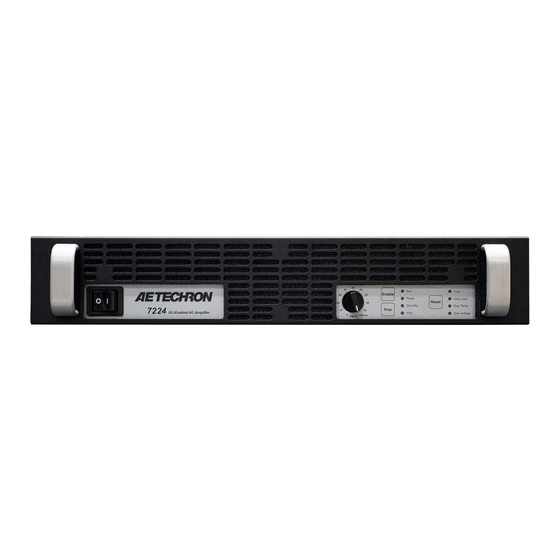
Summary of Contents for Aetechron 7224RLY
- Page 1 7224RLY Operator’s Manual Supplement For Variable, Very-Low-Impedance Loads in Controlled-Current Mode 574.295.9495 | www.aetechron.com 2507 Warren Street, Elkhart, IN 46516...
-
Page 2: Factory Configuration
(see the “DIP Switch Functions The low noise floor, low distortion and minimal and Default Settings” section in this supple- phase error of the 7224RLY make it the ideal am- ment). plifier for power grid modeling. 2. The 7224RLY ships with a multi-pole compen- sation enabled for the compensation setting for Controlled Current mode. - Page 3 OUTPUT (positive) terminals located on the 3-position terminal strip on the amplifier The 7224RLY is designed for pulsed operation and should back panel. The CHASSIS GROUND terminal not be run at high power levels for long periods of time also located on the 3-position terminal strip can be (greater than 5 minutes).
-
Page 4: Connecting The Input Signal
7224RLY OPERATOR’S MANUAL SUPPLEMENT – SECTION A CHASSIS GROUND. This resistor should NOT be anced Input, move the Input Select switch to the removed. WARNING: Removing this resistor right to lift the ground on the connector. can cause dangerous output and/ or damage to Connect your input signal to the amplifier’s unbal-... -
Page 5: Startup Sequence
DIP switch setting and its uses, refer to the “Ad- vanced Configuration” section in the AE Techron 7224 Operator’s Manual. Figure 7.1 – Chart of DIP Switch Functions and Default Settings for 7224RLY Information subject to change 96-8003908 01-25-2024... - Page 6 RESET signal on the I/O Con- nector, to move the amplifier back to a RUN (Opera- tional) condition. When the 7224RLY amplifier is used in Controlled- Populated CUSTOM COMPENSATION Current mode, the current control loop is tuned with an RC network.
-
Page 7: Specifications
Short (unimpeded wire) Sine 10 Specifications The following specifications apply to a 7224RLY Please refer to the 7224RLY datasheet for in- amplifier using the default factory settings. formation about the product’s performance, fea- tures and physical characteristics. The product datasheet is available for download from the AE Techron website at www.aetechron.com. - Page 8 * All loads from 8-ohm to short are stable with 2 mH in series. Input to Output Phase Delay: -0.2 Output Offset Current: Less than 10.0 milliamperes DC peak Out Accuracy: Less than ±1% Figure 10.1 – 7224RLY Back Panel (Version D configuration shown) viii Information subject to change 96-8003908 01-25-2024...


Need help?
Do you have a question about the 7224RLY and is the answer not in the manual?
Questions and answers