
Related Manuals for Aetechron 7234


Summary of Contents for Aetechron 7234
- Page 1 7234 Operator’s Manual Single-Channel Industrial Amplifier for Demanding, High-Power Systems 574.295.9495 | www.aetechron.com 2507 Warren Street, Elkhart, IN 46516...
- Page 3 2507 Warren St. Elkhart, IN, 46516, U.S.A. receive an authorization to return the product for (574) 295-9495 service. All components must be shipped in a factory www.aetechron.c pack or equivalent which, if needed, may be obtained...
-
Page 4: Table Of Contents
Contents 1 Introduction ............................5 1.1 Features ..........................5 1.2 Configuration Options......................5 2 Amplifier Unpacking and Installation ....................6 2.1 Safety First ..........................6 2.2 Unpacking ..........................6 2.3 Installation ..........................6 3 Connections and Startup .......................7 3.1 Other Operation Modes and Configurations................7 3.2 Connecting the Load ......................7 3.3 Connecting the Input Signal ....................8 3.4 Other Back Panel Controls and Connectors ..............9 3.5 Connecting the AC Supply ....................9 3.6 ... -
Page 5: Introduction
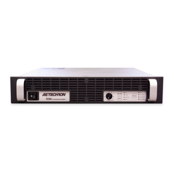
7234 OPERATOR’S MANUAL – SECTION 1 Figure 1.1 – 7234 Front Panel 1 Introduction Performance Overview Congratulations on your purchase of the 7234 power amplifier. AE Techron’s 7234 amplifier is a capable, versatile, and reliable EMC lab partner. Small Signal Bandwidth (8V p-p) DC - 1 MHz This powerful amplifier/battery simulator provides Max Continuous Power, 20 kHz 900 watts RMS up to 28A of long-term DC current with surges of up to 50A and can slew voltages at rates of up to For High-Power Applications to: 100 kHz 100V/μs. DC Power: 28A at 13.5 VDC It is load-tolerant, able to drive most inductive, capacitive, and resistive loads easily. The feature ... -
Page 6: Amplifier Unpacking And Installation
7234 OPERATOR’S MANUAL – SECTION 2 2 Amplifier Unpacking and Installation The 7234 amplifier is a precision instrument that Along with any additional accessories purchased can be dangerous if not handled properly. Lethal by the customer, all 7234 amplifiers ship with the voltages are present in both the AC input supply following: and the output of the amplifier. For this reason, • 7234 Amplifier safety should be your primary concern when you • Power Cord setup and operate this amplifier. • 7234 Operator’s Manual and Quick Start sheet 2.1 Safety First 2.3 Installation Throughout this manual special emphasis is The 7234 amplifiers are packaged in a rugged placed on good safety practices. The following powder-coated steel chassis. This chassis is 2U graphics are used to highlight certain topics that (rack units) tall, and has rack “ears” on each side require extra precaution. of the front panel for mounting to a standard EIA (Electronic Industries Association) rack. Use stan- DANGER dard rack mounting hardware to mount the ampli- fier. Use nylon washers if you wish to protect the DANGER represents the most severe powder-coat finish on the front of the amplifier. ... -
Page 7: Connections And Startup
7234 OPERATOR’S MANUAL – SECTION 3 Figure 3.1 – 7234 Back Panel 3 Connections and Startup first be wired and tested individually in Controlled- This section details the wiring and startup pro- Voltage mode to ensure proper operation. cedures for a single 7234 amplifier operating in Controlled-Voltage mode (factory default). Before For Series operation in Controlled-Voltage connecting the amplifier, make sure the AC power mode, refer to the topic “Multiamp Systems for cord is unplugged. Increased Current or Voltage” in the Applications section of this manual for information on Series WARNING system configuration. ELECTRIC SHOCK HAZARD. For Series operation in Controlled-Current Output potentials can be lethal. Make mode, you should select one amplifier to be oper-... -
Page 8: Connecting The Input Signal
7234 OPERATOR’S MANUAL – SECTION 3 Always use the appropriate wire size and insula- card can easily be removed and replaced with tion for the maximum current and voltage expected alternate SIM cards designed for special applica- at the output. Never connect the output of the tions, when required. amplifier to any other model amplifier, power sup- The SIM BNC card provides both an unbalanced ply, signal source, or other inappropriate load; fire Input BNC jack and a balanced Input “WECO” can result. terminal block connector. (Mating connector for the WECO connector is provided.) Connect your input WARNING signal to the unbalanced or balanced input con- nector as shown in Figure 3.3. Use cables that are ELECTRIC SHOCK HAZARD. high quality and shielded to minimize noise and to Output potentials can be lethal. Make connections only with AC Power OFF guard against possible feedback. -
Page 9: Other Back Panel Controls And Connectors
7234 OPERATOR’S MANUAL – SECTION 3 INTERCONNECT PORTS: The Interconnect ports can be used to provide remote control and moni- toring of the amplifier, and for connecting multiple amps in push/pull or parallel configurations. See the Applications section of this manual for more information. INTERLOCK I/O CONNECTOR: The Interlock Connector can be used to provide remote control and monitoring of the amplifier, and for connect- ing multiple amps in series configurations. See the Applications section of this manual for informa- tion. Figure 3.4 – Input Select Switch Settings for Unbalanced or Balanced Input Connectors IMPORTANT: The Input Select switch can also function as a Ground Lift switch for the BNC Input connector. -
Page 10: Amplifier Operation
7234 OPERATOR’S MANUAL – SECTION 4 4 Amplifier Operation 4.1 Front-Panel Controls This section provides an overview of Front-Panel controls and indicators found on the 7234. 4.1.1 Power Switch The Power Switch controls the AC mains power to the amplifier. Switch to the ON position (|) to turn Figure 4.1 – Power Switch the amplifier on. Switch to the OFF position (O) to turn the amplifier off. See Figure 4.1. The Power Switch also serves as a Breaker. When the Breaker is tripped, the Power Switch moves to a neutral position between ON and OFF. To reset the Breaker, turn the amplifier OFF (O) and then turn it back ON (I). 4.1.2 Gain Control Figure 4.2 – Gain Control The Gain Control Knob increases/decreases the gain from 0 – 100% of the overall Gain. Turn the Gain Control fully clockwise for maximum amplifier to power-up in Standby/Stop mode, please see the output. See Figure 4.2. Advanced Configuration section. -
Page 11: Front-Panel Indicators
7234 OPERATOR’S MANUAL – SECTION 4 If an amplifier is disabled using a Remote Standby dition has been cleared and the amplifier has been switch, the amplifier will be placed in Remote configured for startup in Run mode. If the amplifier Standby mode. To return the amplifier to a Run has been configured for startup in Standby/Stop condition, release the Standby condition using the mode, pressing the Reset button will place the remote switch. See the Applications section of amplifier in Standby/Stop mode. Press the Enable this manual for more information on remote ampli- button to return the amplifier to Run mode. fier operation. 4.2 Front-Panel Indicators Standby/Fault mode (Standby and one or more 4.2.1 Main Status Indicators Fault LEDs lit): The amplifier has been placed in Four Main Status indicators are located on the am- Standby due to an Output, Overload, Over Temp ... - Page 12 7234 OPERATOR’S MANUAL – SECTION 4 Figure 4.5 – Main Status Indicators Indicator is lit Indicator is not lit Indicator may be lit Main Status Indicators State of Operation Action Needed to Return to Run Mode Run mode: The amplifier’s high-voltage transformers are energized and the unit will amplify the input signal. Run mode is initiated Ready by: (1) the Enable push button, or (2) when Standby the amplifier powers up in Run mode (factory Stop default). See the Advanced Configuration...
- Page 13 7234 OPERATOR’S MANUAL – SECTION 4 Figure 4.6 – Fault Status Indicators Indicator is lit Indicator is not lit Indicator may be lit Action Needed to Clear Fault Main Status Fault Status Condition and Return to Indicators Indicators State of Operation Run Mode Output Fault status: This indicates This fault condition cannot be cleared that an Output Fault condition has oc-...
-
Page 14: Back-Panel Controls And Connectors
7234 OPERATOR’S MANUAL – SECTION 4 Back-Panel Controls and Connectors remote voltage sense at the load. It can be useful This section provides an overview of Back-Panel when the voltage at the load must be precise. controls and connectors found on the 7234. Please refer to Figure 4.7 for visual locations. CAUTION AC Supply – Standard 20 amp 3-pin IEC-type male connector. Turn the amplifier OFF before chang- ing DIP switch positions. Some switch Output Terminal Strip – Connect output lines ... -
Page 15: Advanced Configuration
7234 OPERATOR’S MANUAL – SECTION 5 5 Advanced Configuration The 7234 amplifier was designed to offer excep- tions, or for applications requiring mid-level tional versatility in operation. You can choose from amounts of both voltage and current. a range of field-configurable options, including: • Change the maximum amplifier gain from 20:1 to 6:1. • Operate as a stand-alone amplifier or as part of • Operate with variable gain control or at a fixed a multiple-amplifier system. gain setting (20 or 6). • Select DC-coupled or AC-coupled operation. • Configure the amplifier to enter Standby on • Select Controlled-Current or Controlled-Voltage startup modes of operation. • Configure the amplifier to enter Standby when • Enable a 50-kHz low-pass filter. an overload condition occurs. • Configure the bi-level power supply for use in high voltage applications, high current applica- Figure 5.1 – DIP Switch Settings and Descriptions 5.1 DIP Switch Configurations CAUTION The 7234 amplifier provides eight DIP switches ... -
Page 16: Internal Configurations
7234 OPERATOR’S MANUAL – SECTION 5 on Controlled-Current operation, including how to When this switch is in the Down position (default), Electronic Gain Matching is disabled. When the determine and configure a custom compensation Electronic Gain Matching DIP switch is in the Up network, see the Applications section. position, the Electronic Gain Matching function is SW#2: Compensation (CC1/CC2) enabled. When a 7234 amplifier is used in Controlled-Cur- SW#6: Master/Follower rent mode, the current control loop is tuned with an When the Master/Follower DIP switch is in the Up RC network. Place the Compensation DIP switch position (default), the amplifier will function as a in the Up position (default) to enable the factory- stand-alone amplifier or as a Master amplifier in installed RC network (CC1). This network consists a multi-amp system. When this switch is in the of a 68.1 kΩ resistor in series with a 47 nF capaci- Down position, the amplifier will function as a Fol- tor. Place the DIP switch in the Down position to lower amplifier in a multi-amp system. - Page 17 7234 OPERATOR’S MANUAL – SECTION 5 • Configure the amplifier to enter Standby when 5.2.1 Amplifier Top Cover Removal an Overload fault condition occurs. Tool Required Power Supply Board #2 Phillips screwdriver Procedure • Change the amplifier voltage potential for high- 1. Remove power from the amplifier and discon- current or high-voltage operation nect any load from the amplifier outputs. Wait a • Change the bi-level power supply function for minimum of three minutes to allow the ampli- auto, locked low, or locked high operation fier’s capacitors to discharge. The main and power supply boards can be ac- 2. Remove the amplifier’s front grill cover by cessed by removing the amplifier top cover. To firmly pulling the grill cover away from the front remove the amplifier top cover, complete the steps panel. The grill is held by magnets. detailed in the following section. 3. Use the Phillips screwdriver to remove nine (9) DANGER screws: a. Three (3) screws from each side b. ...
- Page 18 Current Opera- tion” in the Applications section of this manual. Fixed or Variable Gain Enable/Stop on Power-up The 7234 amplifier ships with an enabled Gain Control knob, which is located on the amplifier The 7234 amplifier will power-up to Run Mode when a shunt is placed across pins 1 and 2 on the front panel. To disable the Variable Gain control Enable/Stop jumper (default setting). See Figure and set for a Fixed Gain, locate the Gain Control 5.3. To cause the 7234 amplifier to enter Standby Bypass jumper, remove the gain control wire, and (Stop Mode) on power-up, place the shunt across place a shunt across the two pins at that location. pins 2 and 3. See Figure 5.4. Figure 5.4 – Configure for Fixed or Variable Gain Information subject to change 96-8005901_05-26-2021...
- Page 19 7234 OPERATOR’S MANUAL – SECTION 5 Standby on Overload amplifier will continue to operate. To configure the The 7234’s IOC (Input/Output Comparator) Distor- 7234 to move to Standby (Fault mode) when the tion Alert circuit continuously compares the wave- IOC circuit is activated, locate the Overload Latch forms observed at the amplifier input and output. (see Figure 5.5) and place a shunt across the two When a distortion between the two waveforms pins of the jumper. of more than 0.5% occurs, the IOC circuit will activate, and the Overload LED will light, but the Figure 5.5 – Configure for Standby (Fault Mode) on Overload 5.2.3 Configuration Settings Located on the Power Supply Board The following custom settings are configured on and the dual transformers configured in parallel, the Power Supply Board: providing a voltage potential of 90V. • Amplifier Voltage Potential setting (high current During normal operation, the 7234 will use the or high voltage) signal received at input to calculate the expected ...
- Page 20 7234 OPERATOR’S MANUAL – SECTION 5 Figure 5.6 – Power Supply Settings frequency, may require a fixed configuration for operation via user-selectable plugs on the Power maximum continuous operation. For those applica- Supply Board. tions, the Bi-level switch allows the user to select Refer to the chart in Figure 5.7 for recommended the High setting for a fixed series configuration applications and expected output voltage based on with higher voltage potential, or the Low setting for the various configuration settings. a fixed parallel configuration with a lower voltage potential. Accessing the Power Supply Board To access the Power Supply Board, follow the In the same way, the two secondaries in each instructions given previously in this section under transformer can be configured for series (high volt- the topic “Amplifier Top Cover Removal.” The age: 180V) or parallel operation (high current: 90V) ...
- Page 21 7234 OPERATOR’S MANUAL – SECTION 5 Figure 5.9 – Location of Amplifier High-Voltage Transformer Sockets Figure 5.8 – Accessing the Power Supply Board Power Supply Board is located to the right of the Main Board, as shown in Figure 5.8. Changing Amplifier Voltage Potential The amplifier can be configured for High Current (90V) or High Voltage (180V) operation via user- selectable plugs on the Power Supply Board. Complete the following steps to change the ampli- fier voltage potential. Figure 5.10 – J3 and J7 Plug Locations for 1. Locate the two XFMR sections (left of Line High-Current Output Voltage sections) (see Figure 5.9). 2. For High Current (90V) Output (see Figure 5.10). 3. For High Voltage (180V) Output (see Figure 5.11). Changing Bi-Level Power Supply Setting The amplifier provides three Bi-Level switch set- tings: Automatic, High, or Low. The user can ...
- Page 22 7234 OPERATOR’S MANUAL – SECTION 5 SIM card from the amplifier until it is completely clear from the card bay. 4. Locate Bi-Level Power Switch, S1, a black, three-position switch at the rear of the card bay.(See Figure 5.12) 5. Move Black switch to desired setting. If neces- sary, use a pointed, non-metallic object (such as a pen) to help in moving the switch. Figure 5.12 – Bi-Level Power Switch Location a. Automatic – Left b. Low – Middle c. High – Right Information subject to change 96-8005901_05-26-2021...
-
Page 23: Applications
7234 OPERATOR’S MANUAL – SECTION 6 6 Applications The information provided here will instruct you in The procedures outlined in this section assume the wiring of several control and status applica- competence on the part of the reader in terms of tions including: amplifier systems, electronic components, and good electronic safety and working practices. • Remote Enable/Standby • Temperature monitor 6.1 Remote Status and Control using • Current monitor the Interconnect Ports • Voltage monitor CAUTION Figure 6.1 maps the pins used for these applica- tions. NOTE: Both 9-pin D-Sub connectors have the same pin-outs and either port can be used for remote These Application instructions for the Interconnect Ports apply only to units applications. - Page 24 7234 OPERATOR’S MANUAL – SECTION 6 6.1.2 Remote Monitoring of Temperature Using one of the 9-pin D-Sub connectors located on the back panel of the amplifier, you can remote- ly monitor the temperature at the heat-sinks of the amplifier. Remote Monitoring of Temperature Purpose: Use a voltage meter to monitor tempera- ture at the heat-sinks. Method: Connect a voltage meter to monitor the temperature at the heatsinks of the amplifier. Con- nect across Temp (PIN 4) and Ground (PIN 3 or 6). See Figure 6.3. Figure 6.3 – Remote Temperature Monitor Signal Type: AC Level: (VDC X 100) - 273 = degrees Celsius Most digital multimeters have an input impedance IMPORTANT: This circuit has a 1K build-out resis- of 1 megohm and would work well for this applica- tor. Make sure the monitor function has sufficient tion. impedance to avoid accidentally influencing status. ...
-
Page 25: Remote Status And Control Using The Sim Interlock I/O Connector
7234 OPERATOR’S MANUAL – SECTION 6 6.2 Remote Status and Control using the SIM Interlock I/O Connector to provide remote control and monitoring of the AE Techron 7234 amplifiers come with a SIM-BNC amplifier. input module that also contains a female, 25-pin D-Sub connector. This connector can be used The information provided here will instruct you in the wiring of several control and status applica- tions including: • Run/Standby status • Amplifier status: Run, Over-temperature, Over- load, Overvoltage; and Reset after Overload error • Remote Enable/Standby • Current monitor • Temperature monitor Figure 6.6 maps the pins used for these applications. - Page 26 7234 OPERATOR’S MANUAL – SECTION 6 6.2.2 Remote Amplifier Status & Reset of the amplifier when it is forced to Standby due to The SIM Interlock I/O Connector can be used to Over-load conditions. create a circuit to monitor remotely one or more Use a male, 25-pin D-Sub connector and high- amplifier conditions, including Run status, Over- quality wire to build the circuit. Figure 6.8 sche- temperature, Overload and Overvoltage. The cir- matic details the circuit and components required cuit can also be constructed to allow remote reset for all status and reset functions.
- Page 27 7234 OPERATOR’S MANUAL – SECTION 6 Remote Signal of OverVoltage Condition Remote Signal of Run Condition Purpose: LED, when lit, signals Run state. Purpose: LED, when lit, signals Overvoltage condition. Method: Use a 6mA series resistor of 4.02K-ohm Method: Use a 6mA series resistor of 4.02K-ohm for LED or OPTO, tie Run (PIN 12) to –24V source for LED or OPTO, tie OverVoltage Out (PIN 24) to (PIN 13). –24V source (PIN 13). Signal Type: DC Signal Type: DC Level when Asserted: –24V Level when Asserted: –24V Level when Deasserted: 0V...
- Page 28 7234 OPERATOR’S MANUAL – SECTION 6 When Interlock (PIN 4) is shorted to Digital Ground IMPORTANT: The amplifier must be configured for (PIN 17), amplifier is placed in Standby mode. Ready mode at startup (factory default) or the Run When switch is open, amplifier is released to the button must be pressed at the amplifier front panel Run condition. at startup. The Remote Enable/Standby circuit will Signal Type: DC not function if the Startup to Standby Latch has Level when Asserted: 0 to 8 V been activated on the amplifier. Level when Deasserted: 10 to 15 V 6.2.4 Remote Monitoring of Current Using the SIM-BNC Interlock connector located on the back panel of the amplifier, you can remotely monitor current output. Remote Monitoring of Current Output Purpose: Use a voltage meter to monitor output current.
- Page 29 7234 OPERATOR’S MANUAL – SECTION 6 6.2.5 Remote Monitoring of Tempera- ture Using the SIM-BNC Interlock connector located on the back panel of the amplifier, you can remotely monitor the temperature at the heat-sinks of the amplifier. Remote Monitoring of Temperature Purpose: Use a voltage meter to monitor temper- ature at the heat-sinks. Method: Connect a voltage meter to monitor the temperature at the heatsinks of the amplifier. Con- nect across PIN 9 (TEMP MONITOR) and PIN 10 (Sampled Common). See Figure 6.12. Signal Type: AC Level: (VDC * 100) - 273 = degrees Celsius IMPORTANT: This circuit has a 1K build-out resis- tor. Make sure the monitor function has sufficient Figure 6.12 – Remote Monitoring of Temperature impedance to avoid accidentally influencing status. Most digital multimeters have an input impedance of 1 megohm and would work well for this applica- tion.
-
Page 30: Controlled Current Operation
7234 OPERATOR’S MANUAL – SECTION 6 6.3 Controlled Current Operation The procedures outlined in this section assume competence on the part of the reader in terms of amplifier systems, electronic components, and good electronic safety and working practices. 6.3.1 Controlled-Voltage vs. Controlled- Current Modes of Operation AE Techron 7234 amplifiers can be field-configured to operate as Voltage Amplifiers (Voltage-Con- Figure 6.13 – Input to Output Comparison, trolled Voltage Source) or as Transconductance Controlled-Voltage Operation Amplifiers (Voltage-Controlled Current Source). The mode selection is made via a DIP switch on the amplifier’s back panel. See the Advanced Configuration section for more information. When configured as a Controlled-Voltage source (voltage amplifier), the amplifier will provide an output voltage that is constant and proportional to the control (input) voltage. If the load’s imped- ance changes, the amplifier will seek to maintain this ratio of input to output voltage by increasing or Figure 6.14 – Input to Output Comparison, decreasing the current it produces, as long as it is ... - Page 31 7234 OPERATOR’S MANUAL – SECTION 6 for some applications, the compensation setting rent (CC) mode of operation. When operating the may also be adjusted in the field. The following amplifier in Controlled Voltage (CV) mode, com- section describes methods for determining and pensation is not required. However, when operat- setting proper compensation when operating in ing in Controlled Current (CC) mode, the amplifier Controlled-Current mode. load becomes an integral part of the system. In order to ensure system stability and to control 6.3.3 Controlling Compensation for available bandwidth, compensation via an RC CC Operation network is required for CC operation. The following AE Techron 7234 amplifiers can be configured for steps will allow you to compensate your amplifier either Controlled Voltage (CV) or Controlled Cur- for operation in CC mode safely and effectively. STEP 1: Check Amplifier Operation in CV mode.
- Page 32 7234 OPERATOR’S MANUAL – SECTION 6 STEP 3: Determine if Default or Custom Compensation is Required. If your load inductance is between 200 microHen- 5 ohms, then you must calculate your required ries and 1 milliHenry, and your load resistance compensation. If, after calculating your required is less than 5 ohms, then you can likely use the compensation, you determine that the default com- default compensation provided by the amplifier’s pensation will be insufficient for your load, then you factory-installed RC network. will need to calculate and then enable and install a custom RC network.
- Page 33 7234 OPERATOR’S MANUAL – SECTION 6 Amplifier Top Cover Removal c. Two (2) screws from the front (after the grill Tool Required cover is removed. #2 Phillips screwdriver 4. Lift the cover straight up to remove it and set it aside. DANGER 5. To replace the top cover, slide the cover in to place on the amplifier and replace the nine Uninsulated terminals with AC mains screws. potential are exposed when the top cover is removed. Do not proceed until 6. Position the grill near the front panel and snap ...
- Page 34 7234 OPERATOR’S MANUAL – SECTION 6 STEP 7: Optimizing the Compensation Values. Remember the load you are connecting is a If the output current waveform is rounded, the circuit is overdamped: You have too little compen- part of the system and the amplifier should not be turned on without the load being connected. sation and should increase resistance (see Figure 6.19). After installing the components, check to ensure that the Operation DIP switch (SW#1) is set to Current mode, then power up the amplifier without signal input.
-
Page 35: Multi-Amp Systems For Increased Voltage Or Current
Three in Series 474 Vp Accessories for Push/Pull and Parallel Two in Parallel 90 Ap systems will only work with 7234 ampli- fiers with a serial number ending Three in Parallel 135 Ap in “B.” Units with a serial number... - Page 36 7234 OPERATOR’S MANUAL – SECTION 6 Use Only 7234 Amplifiers Make sure both amplifiers are disconnected Use only AE Techron 7234 amplifers to construct from AC power. a 7234 multiamp system. Do not combine different CAUTION models of AE Techron amplifiers in the same sys- tem or use amplifiers made by another manufac- Turn the amplifier OFF before chang- turer in a 7234 multiamp system. Such improper ing DIP switch positions. Some switch connections could damage the amplifiers. changes could result in amplifier damage. Use Correct Wiring Required DIP Switch Settings Never directly connect one amplifier’s OUTPUT ...
- Page 37 1 2 3 4 5 6 7 8 KEY FOR DIP SWITCH SETTINGS: WECO SYSTEM REQUIREMENTS: REQUIRED (2) 7234 Amplifiers DEFAULT 3110A or other (1) 7234 PUSH/PULL DB-9 CABLE KIT OPTIONAL Signal Generator (69-8005917) NOT RECOMMENDED Figure 6.23 – Configuration and Wiring for Push/Pull Operation 2. Connect from a signal generator to the BNC or er amplifier’s back-panel SAMPLED COMMON WECO signal input connector on the Master ...
- Page 38 Follower amplifier (Follower #1). tions that can be optionally enabled for use during 2. If additional Follower amplifiers are to be used, multi-amp operation. The Master amplifier controls connect an additional Parallel DB9 cable from these functions for the multi-amp system, so you the back-panel Interconnect B port on Fol- only need to adjust these settings on the Master lower #1 amplifier to the Interconnect A port on amplifier. the second Follower amplifier (Follower #2). Repeat this set with an additional Parallel DB9 cable for the third Follower amplifier, if used. 3. Connect from a signal generator to the BNC or WECO signal input connector on the Master amplifier’s back panel SIM-BNC input card. 4. Using the red and black output cables from the 7234 Parallel Wiring Kit, connect one cable leg of the black (ground) output cable to each of the amplfier’s back-panel SAMPLED COM- MON connectors, and then connect the cable’s terminated end to the ground terminal of your load. Next, connect one cable leg of the red Figure 6.24 – DIP Switch Settings for (positive) output cable to each of the amplfier’s Parallel Configuration Information subject to change 96-8005901_05-26-2021...
- Page 39 7234 OPERATOR’S MANUAL – SECTION 6 PARALLEL CONFIGURATION 7234 AMPLIFIERS 7234 AMP #4 - FOLLOWER AMPLIFIER OUTPUTS INPUT & MULTIAMP CONNECT OUTPUT COMMON SAMPLED COMMON 2.7-ohm resistor CHASSIS GROUND DIP SWITCH SETTINGS: 1 2 3 4 5 6 7 8 7234 AMP #3 - FOLLOWER AMPLIFIER OUTPUTS INPUT &...
- Page 40 7234 OPERATOR’S MANUAL – SECTION 6 back-panel OUTPUT connectors, and then connect the cable’s terminated end to the posi- tive terminal of your load. 6.4.4 Series Configuration To configure and connect up to three amplifiers for operation in a series configuration, begin by desig- nating one amplifier as the Master amplifier. Up to three 7234 amplifiers can be configured for series operation, so all other amplifiers in the system will operate as Follower amplifiers.Consider placing labels on each amplifier’s back panel to clarify the Figure 6.26 – DIP Switch Settings for amplifier designation during setup and operation Series Configuration (Master, Follower #1, Follower #2). SW#3 - Low-Pass Filter (50 kHz): Set DIP switch Make sure all amplifiers are disconnected from #3 on the Master amplifier in the DOWN position to AC power. enable.
- Page 41 7234 OPERATOR’S MANUAL – SECTION 6 used as an unbalanced input via jumpers located CAUTION on the input card. Jumper locations for the SIM-BNC-OPTOC card After turning the amplifier off, let the unit sit for 3-5 minutes before removing the are shown in Figure 6.27. input card. This will allow the electrical charge in the power supply capacitors to Jumpers 4 & 5: When J4 and J5 are Closed, the ...
- Page 42 2. Connect from a signal generator to the BNC or connector. WECO signal input connector on the Master amplifier’s back panel SIM-BNC-OPTOC input card. TWO AMPLIFIERS 7234 IN SERIES CONFIGURATION AMPLIFIERS 7234 AMP #2 - FOLLOWER AMPLIFIER OUTPUTS INPUT & MULTIAMP CONNECT OUTPUT COMMON SAMPLED DIP SWITCH SETTINGS: COMMON REMOVE 1 2 3 4 5 6 7 8 2.7-ohm...
- Page 43 7234 OPERATOR’S MANUAL – SECTION 6 THREE AMPLIFIERS 7234 IN SERIES CONFIGURATION AMPLIFIERS 7234 AMP #3 - FOLLOWER AMPLIFIER OUTPUTS INPUT & MULTIAMP CONNECT OUTPUT COMMON SAMPLED DIP SWITCH SETTINGS: COMMON REMOVE 1 2 3 4 5 6 7 8 2.7-ohm CHASSIS resistor GROUND 7234 AMP #2 - FOLLOWER AMPLIFIER OUTPUTS INPUT &...
- Page 44 7234 OPERATOR’S MANUAL – SECTION 6 all amplifiers in the system must be considered to fier has been configured for startup in Run mode. determine the current status and the necessary However, pressing the Reset button on other am- remedies to return the system to operational status plifiers in the system (not reporting a fault condi- when a fault condition occurs. tion) will NOT clear the fault condition. Refer to the “Fault Status Indicators” section for information Enable, Stop and Reset Buttons on how to clear fault conditions and restore ampli- The following details the results when each of the fier operation. three Push Buttons are pressed on an amplifier front panel in a multi-amp system. If the amplifier reporting the fault condition has been configured for startup in Stop mode, pressing Enable – In multi-amp systems that have been ...
- Page 45 7234 OPERATOR’S MANUAL – SECTION 6 Figure 6.31 – Main Status Indicators for Multi-Amplifier Systems Indicator is lit Indicator is not lit Indicator may be lit Main Status of One or Main Status of More Amps in Other Amps in Action Needed to Return to...
- Page 46 7234 OPERATOR’S MANUAL – SECTION 6 Figure 6.32 – Fault Status Indicators for Multi-Amplifier Systems Indicator is lit Indicator is not lit Indicator may be lit One or More Amps in System Other Amps in System Action Needed to Clear Fault Main Status Fault Status...
- Page 47 7234 OPERATOR’S MANUAL – SECTION 6 One or More Amps in System Other Amps in System Action Needed to Clear Fault Main Status Fault Status Main Status Fault Status Condition and Re- Indicators Indicators Indicators Indicators State of Operation turn to Run Mode Over Temp status: To reset after an Over ...
-
Page 48: Maintenance
7234 OPERATOR’S MANUAL – SECTION 7 7 Maintenance • Vacuum cleaner Damp cloth (use water only or a mild soap • Simple maintenance can be performed by the user diluted in water) to help keep the equipment operational. The fol- To ensure adequate cooling and maximum effi- lowing routine maintenance is designed to prevent ciency of the internal cooling fans, the amplifier’s problems before they occur. See the Trouble- front and rear grills should be cleaned periodically. shooting section, for recommendations for re- To clean the amplifier grills and filter, complete the storing the equipment to operation after an error following steps: condition has occurred. 1. Turn completely down (counter-clockwise) all ... -
Page 49: Troubleshooting
7234 OPERATOR’S MANUAL – SECTION 8 8 Troubleshooting 6. Look for any foreign objects lodged inside the unit. 8.1 Introduction & Precautions 7. Inspect the entire lengths of wires and ribbon cables for breaks or other physical damage. This section provides a set of procedures for 8. If there is any physical damage to the amplifier, identifying and correcting problems with the 7234 please return it to AE Techron for repair. amplifier. Rather than providing an exhaustive and detailed list of troubleshooting specifications, this 8.3 No Signal section aims to provide a set of shortcuts intended Missing Output signal may be caused by one of to get an inoperative amplifier back in service as the following: quickly as possible. 1. The Master/Follower DIP switch (SW#6) is set The procedures outlined in this section are direct- to the Follower (Down) position. The amplifier ed toward an experienced electronic technician; should only be configured for Follower opera- it assumes that the technician has knowledge of tion if it is in a multi-amplifier system; otherwise typical electronic repair and test procedures. the Master/Follower DIP switch should be set to the Master (Up) position. See the Advanced Please be aware that the 7234 will undergo fre- Configuration section in this manual for more quent engineering updates. As a result, modules ... -
Page 50: Standby And Stop Leds Remain Illuminated
2. Visually inspect fans to assure correct op- Standby mode by another device. Release the eration while amplifier is On (I). When an remote switchor device to return the amplifier to OverTemp fault occurs, the amplifier fans will Run mode. For more information on 7234 Remote automatically be placed in continuous high- Operation, see the Applications section in this speed operation. Any inoperative, visibly slow, or reverse-spinning fan should be replaced. manual. Please see the Factory Service information at 8.7 Standby LED Remains Illuminated the end of this section. -
Page 51: Factory Service
7234 OPERATOR’S MANUAL – SECTION 8 Factory Service. See the Factory Service infor- All service units must be given Return Authoriza- tion by AE Techron, Inc. before being returned. mation at the end of this section. Return Authorizations can be requested on our website or by contacting our Customer Service CAUTION Department. Shut off the signal source before reset- Please take extra care when packaging your am- ting the amplifier. Try resetting the Fault plifier for repair. It should be returned in its original condition only once. If the Fault condi- tion does not clear after one reset, STOP. -
Page 52: Appendix A: Alternate Interconnect Ports Application Wiring
7234 OPERATOR’S MANUAL – SECTION A Appendix A: Alternate Interconnect Ports Application Wiring Remote Status and Control using the Interconnect Ports For Units with Serial Numbers Ending in “A” The information provided here will instruct you in CAUTION the wiring of control and status applications includ- ing: These Application instructions for the • Remote Enable/Standby Interconnect Ports apply only to units with a serial number ending in “A.”... - Page 53 7234 OPERATOR’S MANUAL – SECTION A Remote Monitoring of Temperature Most digital multimeters have an input impedance of 1 megohm and would work well for this applica- Using one of the 9-pin D-Sub connectors located tion. on the back panel of the amplifier, you can remote- ly monitor the temperature at the heat-sinks of the amplifier. Purpose: Use a voltage meter to monitor tempera- ture at the heat-sinks. Method: Connect a voltage meter to monitor the temperature at the heatsinks of the amplifier. Con- nect across Temp (PIN 6) and Ground (PIN 3. See Figure A.3. Signal Type: AC Level: (VDC X 100) - 273 = degrees Celsius IMPORTANT: This circuit has a 1K build-out resis- tor. Make sure the monitor function has sufficient impedance to avoid accidentally influencing status. Figure A.3 – Remote Temperature Monitor Remote Monitoring of Current Output Using one of the 9-pin D-Sub connectors located ...
Need help?
Do you have a question about the 7234 and is the answer not in the manual?
Questions and answers