Sign In
Upload
Manuals
Brands
Aetechron Manuals
Amplifier
7212
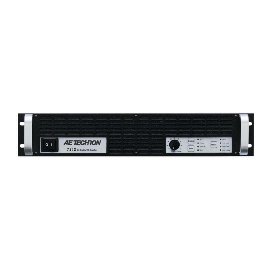
Aetechron 7212 Manuals
Manuals and User Guides for Aetechron 7212. We have
1
Aetechron 7212 manual available for free PDF download: Operator's Manual
Aetechron 7212 Operator's Manual (48 pages)
Four-Quadrant Power Amplifier for Power Utility Testing
Brand:
Aetechron
| Category:
Amplifier
| Size: 3 MB
Table of Contents
Table of Contents
4
1 Introduction
6
Features
6
Figure 1.1 - 7212 Front Panel
6
2 Amplifier Unpacking and Installation
7
Safety First
7
Unpacking
7
Installation
7
3 Connections and Startup
8
Other Operation Modes and Configurations
8
Connecting the Load
8
Figure 3.1 - 7212 Back Panel
8
Connecting the Input Signal
9
Figure 3.2 - Closeup of the Output Terminals
9
Figure 3.3 - Connecting the Load
9
Figure 3.4 - Closeup of SIM Card
9
Figure 3.5 - Wiring and Internal Connections for BNC and Terminal Block Connectors
9
Connecting the AC Supply
10
Start-Up Procedure
10
Figure 3.6 - Closeup of AC Mains Outlet
10
Figure 3.7 - Sample of Configurations Setting Label
10
4 Amplifier Operation
11
Front-Panel Controls
11
Figure 4.1 - Power Switch
11
Figure 4.2 - Gain Control
11
Figure 4.3 - Push Buttons
11
Front-Panel Indicators
12
Figure 4.4 - Indicators
12
Figure 4.5 - Main Status Indicators
12
Figure 4.6 - Fault Status Indicators
13
Back-Panel Controls and Connectors
14
Figure 4.7 - Back Panel Controls and Connectors
14
5 Advanced Configuration
15
Configuration Access Panel
15
Configuration Settings Located on the Main Board
15
Figure 5.1 - Access Panel Screw Locations
15
Figure 5.2 - Main Board Location Inside Access Panel
16
Figure 5.3 - Master/Follower Setting
16
Figure 5.4 - Gain Trim Control
16
Figure 5.5 - Controlled-Voltage/Controlled-Current Mode Setting
17
Figure 5.6 - Compensation Setting
17
Figure 5.7 - Run Mode/Stop Mode on Power-Up Setting
17
Configuration Settings Located on the Power Supply Board
18
Figure 5.8 - Standby Mode on over Load Setting
18
Figure 5.9 - Accessing the Power Supply Board
18
Figure 5.10 - Location of Amplifier High-Voltage Transformer Sockets
19
Figure 5.11 - J3 and J7 Plug Locations for High-Current Output
19
Figure 5.12 - J4 and J8 Plug Locations for High-Voltage Output
19
Figure 5.13 - Bi-Level Power Switch Location
19
6 Applications
20
Remote Status and Control Using the SIM Interlock I/O Connector
20
Figure 6.1 - Remote Status and Control Pinouts
20
Figure 6.2 - Remote Run/Standby Monitor
20
Figure 6.3 - Remote Status and Reset Schematic
21
Figure 6.4 - Remote Enable/Standby
22
Figure 6.5 - Remote Voltage Monitoring
23
Figure 6.6 - Remote Current Monitoring
23
Controlled Current Operation
24
Figure 6.7 - Remote Current Monitoring, Alternate Method
24
Figure 6.8 - Input to Output Comparison, Controlled-Voltage Operation
24
Figure 6.9 - Input to Output Comparison, Controlled-Current Operation
25
Figure 6.10 - Factory-Installed Default RC Network
25
Figure 6.11 - Custom Compensation Location
27
Figure 6.12 - Compensation Effects on Waveform
27
Multi-Amplifier Systems
28
Figure 6.13 - Square Wave Showing a Decrease in R Is Required
28
Figure 6.14 - Square Wave Showing an Increase in R Is Required
28
Figure 6.15 - Square Wave Showing an Increase in C Is Required
28
Figure 6.16 - Main Status Indicators for Multi-Amplifier Systems
31
Figure 6.17 - Fault Status Indicators for Multi-Amplifier Systems
32
7 Amplifier Signal Flow
38
Input Signals
38
AC Mains Power
38
Figure 7.1 - Board-Level Functional Block Diagram
38
8 Maintenance
39
Clean Amplifier Filter and Grills
39
9 Troubleshooting
40
Introduction & Precautions
40
Visual Inspection
40
Figure 9.1 - +VCC and -VCC Point Locations
40
No Signal
41
No Leds Illuminated or no Fans
41
Overvoltage LED Lit
41
Standby LED Remains Illuminated
41
Figure 9.2 - Fuse F1 Location
41
Figure 9.3 - Interlock I/O Connector
41
Amplifier Overheats (over Temp Fault Condition)
42
Fault LED Is Illuminated
42
Factory Service
42
10 Specifications
44
Figure 10.1 - Voltage Potential Vs. Frequency
45
Figure 10.2 - Frequency Response
45
Advertisement
Advertisement
Related Products
Aetechron 7548
Aetechron 7794
Aetechron 7796
Aetechron 7228
Aetechron 7114
Aetechron 7548RLY
Aetechron 7796RLY
Aetechron 7234
Aetechron 7220 Series
Aetechron 7224
Aetechron Categories
Amplifier
Transformer
Inverter
Test Equipment
Relays
More Aetechron Manuals
Login
Sign In
OR
Sign in with Facebook
Sign in with Google
Upload manual
Upload from disk
Upload from URL