Sign In
Upload
Download
Table of Contents
Contents
Add to my manuals
Delete from my manuals
Share
URL of this page:
HTML Link:
Bookmark this page
Add
Manual will be automatically added to "My Manuals"
Print this page
×
Bookmark added
×
Added to my manuals
Manuals
Brands
Aetechron Manuals
Amplifier
7548
Operator's manual
Aetechron 7548 Operator's Manual
Single-channel industrial amplifiers for demanding, high-power systems
Hide thumbs
1
2
3
4
5
6
Table Of Contents
7
8
9
10
11
12
13
14
15
16
17
18
19
20
21
22
23
24
25
26
27
28
29
30
31
32
33
34
35
36
37
38
39
40
page
of
40
Go
/
40
Contents
Table of Contents
Troubleshooting
Bookmarks
Table of Contents
Declaration of Conformity
Table of Contents
1 Introduction
Features
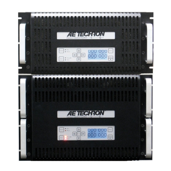
Figure 1.1 - 7548 Front Panel
2 Amplifier Setup
Safety First
Unpacking
Installation
Connecting the Load
Figure 2.1 - Connecting the Load
Figure 2.2 - Close-Up of the Output Terminal Resistor
Connecting the Input Signal
Figure 2.3 - Close-Up of SIM Card
Figure 2.4 - Wiring for Unbalanced or Balanced Input Connector
Connecting the AC Supply
Start-Up Procedure
Figure 2.5 - 208V 3-Phase AC Mains Wiring
Figure 2.6 - 380/400/415V 3-Phase AC Mains Wiring
3 Amplifier Operation
Front-Panel Controls & Display
Figure 3.1 - Front Panel Controls and Display
Input Buttons
Front-Panel Indicators
Figure 3.2 - Front Panel Indicators
Figure 3.3 - Main Status Indicators for Stand-Alone Amplifiers
Navigation Buttons
Figure 3.4 - Fault Status Indicators for Stand-Alone Amplifiers
Figure 3.5 - Main Status Indicators for Multi-Amplifier Systems
Figure 3.6 - Fault Status Indicators for Multi-Amplifier Systems
Back-Panel Controls and Connectors
Figure 3.7 - Back Panel Controls and Connectors
4 Advanced Configuration
Factory Defaults
Accessing the Main Board
Configuration Settings Located on the Main Board
Figure 4.1 - Master or Slave Setting
Figure 4.2 - Gain Trim Control
Figure 4.3 - Controlled-Voltage or Controlled-Current Mode Setting
Figure 4.4 - Compensation Setting
Figure 4.5 - Ready/Run Mode or Standby Mode on Power-Up Setting
Figure 4.6 - Standby Mode on Overtemp Setting
Figure 4.7 - Standby Mode on Overload Setting
Adjusting the Bi-Level Power Supply Switch
Figure 4.8 - Bi-Level Power Switch Location
5 Applications
Remote Status and Control Using the SIM Interlock I/O Connector
Figure 5.1 - Remote Status and Control Pinouts
Figure 5.2 - Remote Run/Standby Monitor
Figure 5.3 - Remote Status and Reset Schematic
Figure 5.4 - Remote Enable/Standby
Figure 5.5 - Remote Voltage Monitoring
Figure 5.6 - Remote Current Monitoring
Controlled Current Operation
Figure 5.7 - Remote Current Monitoring, Alternate Method
Figure 5.8 - Input to Output Comparison, Controlled-Voltage Operation
Figure 5.9 - Input to Output Comparison, Controlled-Current Operation
Figure 5.10 - Factory-Installed Default RC Network
Figure 5.11 - Custom Compensation Location
Figure 5.12 - Compensation Effects on Waveform
Multi-Amplifier Systems
Figure 5.13 - Square Wave Showing a Decrease in R Is Required
Figure 5.14 - Square Wave Showing an Increase in R Is Required
Figure 5.15 - Square Wave Showing an Increase in C Is Required
6 Maintenance
Clean Amplifier Filter and Grills
7 Troubleshooting
Introduction & Precautions
Visual Inspection
Figure 7.1 - +VCC and -VCC Point Locations
Figure 7.2 - Amplifier Cover Removed for Inspection
No Signal
No Leds Illuminated or no Fans
Overvoltage Warning Message
Standby LED Remains Illuminated
Figure 7.3 - Fuse F1 Location
Figure 7.4 - Interlock I/O Connector
Amplifier Overheats (over Temp Fault Condition)
Figure 7.5 - +TEMP and -TEMP Test Point Locations
Fault LED Is Illuminated
Factory Service
8 Specifications
Advertisement
Quick Links
Download this manual
7548/7794/7796
Operator's Manual
Single-Channel Industrial Amplifiers for Demanding, High-Power Systems
APPLIES TO UNITS WITH MAINBOARD PART NUMBER 65-7796135-3
574.295.9495 |
www.aetechron.com
2507 Warren Street, Elkhart, IN 46516
Table of
Contents
Previous
Page
Next
Page
1
2
3
4
5
Advertisement
Table of Contents
Need help?
Do you have a question about the 7548 and is the answer not in the manual?
Ask a question
Questions and answers
Related Manuals for Aetechron 7548
Amplifier Aetechron 7794 Operator's Manual
Single-channel industrial amplifiers for demanding, high-power systems (40 pages)
Amplifier Aetechron 7796 Operator's Manual
Single-channel industrial amplifiers for demanding, high-power systems (40 pages)
Amplifier Aetechron 7228 Operator's Manual
Single-channel industrial amplifier for demanding, high-power systems (55 pages)
Amplifier Aetechron 7114 Operating Manual
Precision industrial ac/dc amplifier (33 pages)
Amplifier Aetechron 7548RLY Operator's Manual
(10 pages)
Amplifier Aetechron 7548RLY Operator's Manual Supplement
(5 pages)
Amplifier Aetechron 7212 Operator's Manual
Four-quadrant power amplifier for power utility testing (48 pages)
Amplifier Aetechron 7234 Operator's Manual
Single-channel industrial amplifier for demanding, high-power systems (53 pages)
Amplifier Aetechron 7220 Series Operator's Manual
Single-channel industrial amplifiers (71 pages)
Amplifier Aetechron 7224 Operator's Manual
(88 pages)
Amplifier Aetechron 7224RLY Operator's Manual Supplement
Dc enabled ac amplifier (8 pages)
Amplifier Aetechron 2110 Operator's Manual
Gradient amplifiers (45 pages)
Amplifier Aetechron 2105 Operator's Manual
Gradient amplifier (37 pages)
Amplifier Aetechron 8704 Operator's Manual
(37 pages)
Amplifier Aetechron 8700 Series Operator's Manual
Ultra-wide-bandwidth, high-power switch-mode amplifiers (41 pages)
Amplifier Aetechron 9100 Series Operator's Manual
Wide-bandwidth, high-power, single-channel digital amplifiers (24 pages)
This manual is also suitable for:
7794
7796
Table of Contents
Print
Rename the bookmark
Delete bookmark?
Delete from my manuals?
Login
Sign In
OR
Sign in with Facebook
Sign in with Google
Upload manual
Upload from disk
Upload from URL


Need help?
Do you have a question about the 7548 and is the answer not in the manual?
Questions and answers