
Related Manuals for Aetechron 9100 Series


Summary of Contents for Aetechron 9100 Series
- Page 1 9100 Series Operator’s Manual Wide-Bandwidth, High-Power, Single-Channel Digital Amplifiers 574.295.9495 | www.aetechron.com 2507 Warren Street, Elkhart, IN 46516...
- Page 3 2507 Warren St. Elkhart, IN, 46516, U.S.A. receive an authorization to return the product for (574) 295-9495 service. All components must be shipped in a factory www.aetechron.com pack or equivalent which, if needed, may be obtained...
-
Page 4: Table Of Contents
Contents 1 Introduction ............................5 1.1 Features ..........................5 2 Amplifier Unpacking and Installation ....................6 2.1 Safety First ..........................6 2.2 Unpacking ..........................6 2.3 Installation ..........................6 3 Connections and Startup .......................7 3.1 Connecting the Load ......................7 3.2 Connecting the Input Signal ....................7 3.3 Optional Controls and Connectors ..................8 3.4 Connecting the AC Supply ....................8 4 ... -
Page 5: Introduction
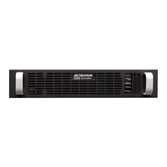
9100 SERIES OPERATOR’S MANUAL – SECTION 1 Figure 1.1 – 9105 Front Panel 1 Introduction Performance Overview Congratulations on your purchase of a 9100 Series digital power amplifier. 9100 Series amplifiers are Bandwidth DC - 250 kHz 200Vp, DC-to-250 kHz capable amplifiers that of- fer a unique combination of switch-mode efficiency Minimum Drop/Rise Time 5µs and linear-amplifier-like fidelity in a single, compact package. They are able to drive virtually any type Slew Rate Up to 150 V/µs of load without a reduction in rated power, with low distortion and low DC drift. They are also fast Max Voltage 0 to 200 V enough to meet 5µs surge and dropout require-... -
Page 6: Amplifier Unpacking And Installation
9100 SERIES OPERATOR’S MANUAL – SECTION 3 Figure 2.1 – 9105 Back Panel 2 Amplifier Unpacking and Installation materials as evidence of damage and/or for return- The 9100 series amplifier is a precision instrument that can be dangerous if not handled properly. Le- ing the amplifier for repair. thal voltages are present in both the AC input sup- 2.3 Installation ply and the output of the amplifier. For this reason, safety should be your primary concern when you The 9100 series amplifier is packaged in a rugged setup and operate this amplifier. powder-coated chassis. This chassis is 2U (rack units) tall, and has rack “ears” on each side of the 2.1 Safety First front panel for mounting to a standard EIA (Elec- tronic Industries Association) rack. Use standard Throughout this manual special emphasis is placed on good safety practices. The following rack mounting hardware to mount the ampli- graphics are used to highlight certain topics that fier. Use nylon washers if you wish to protect the powder-coat finish on the front of the amplifier. require extra precaution. Optionally, the amplifier can be placed on a WARNING bench top; please keep in mind that the protective powder-coating can be scratched when placed WARNING alerts you to hazards that could result in severe injury or death. -
Page 7: Connections And Startup
9100 SERIES OPERATOR’S MANUAL – SECTION 4 3 Connections and Startup This section details the wiring and startup pro- cedures for an 9100 series amplifier operating in Controlled-Voltage mode (factory default). Before connecting the amplifier inputs and outputs, make sure AC power is disconnected. Testing Before Controlled-Current Operation IMPORTANT: If your application requires Con- trolled Current operation, the 9100 series amplifier Figure 3.1 – Connecting the Load first should be wired and tested in Controlled- Voltage mode to verify that the amplifier and input Be sure to install the output safety cover after wir- signal are operating correctly. Once proper opera- ing the output connections. See Figure 3.2. -
Page 8: Optional Controls And Connectors
9100 SERIES OPERATOR’S MANUAL – SECTION 4 3.3.3 Remote Connectors In addition, your 9100 series amplifier provides a balanced “WECO” terminal block connector for sig- Two DB9 connectors are provided on the SIM-91 nal input on the back-panel SIM (Specialized Input module for remote control and monitoring of the Module). The SIM-91 module comes standard with amplifier output, Please refer to the Applications all 9100 series amplifiers, but other SIM modules section of this manual for more information. may be used instead for specialized applications. Information on alternate SIM modules will be found WARNING on a separate information sheet provided with the product, where applicable. The risk of lethal ELECTRICAL SHOCK exists when connecting AC mains! Disconnect the source before connect- Connect your input signal source to the balanced ... - Page 9 9100 SERIES OPERATOR’S MANUAL – SECTION 4 LINE 1 LINE 2 / NEUTRAL Figure 3.5 – AC Mains Barrier Strip Wiring Start-up Procedure 1. Turn down the level of your signal source. 2. Press the front-panel Standby-Run switch to the Run position to ener- gize the amplifier. 3. Wait until the Run/Standby indicator turns solid green. 4. Adjust your input signal level to achieve the desired output level. Information subject to change 96-8007379_01-31-2024...
-
Page 10: Amplifier Operation
4 Amplifier Operation operation when the input voltage is brought within the operating range of the amplifier. 4.1 Front-Panel Controls and Indicators 2. Overtemp condition: Remove the input signal This section provides an overview of Front-Panel from the amplifier and leave the amplifier with controls and indicators found on the 9100 series the Standby-Run switch in the Run position amplifier. Refer fo Figure 4.1 for component loca- and with the fans operating to cool the ampli- tions. fier. When the amplifier’s internal temperature drops to less than 100°C, the amplifier will ... -
Page 11: Back-Panel Controls & Connectors
4.1.5 Overtemp Indicator Back-Panel Controls & Connectors The amplifier monitors the temperature inside the This section provides an overview of Back-Panel high-voltage transformers and in the output stage controls and connectors found on the 9100 series heat sinks. The amber Overtemp indicator will light amplifier. Please refer to Figure 4.2 for component and the amplifier will be placed in Standby mode locations. when the temperature sensors detect a condition Configuration DIP Switches –... - Page 12 9100 SERIES OPERATOR’S MANUAL – SECTION 5 Balanced WECO Input Connector – This input DIP switches allows the amplifier to be configured option provides a balanced input. with one of eight levels of synthetic impedance. See the “Advanced Configuration” section for Remote Connectors – These two 9-pin D-sub more information. connectors, labeled Interconnect A and Intercon- nect B, can be used to set up a Safety Interlock Output Terminals – Connect output lines from the circuit to automatically place the amplifier in load to this pair of high-current output terminals Standby mode when tripped. See the “Applica- using #10 spade or ring terminals. tions” section for more information. AC Power Input – Three-terminal barrier strip Synthetic Impedance DIP Switches –...
-
Page 13: Advanced Configuration
50 µH to 500 µH; or CC2, de- Three additional DIP switches used to enable syn- signed for loads from 500 µH to 1.5 mH. thetic impedance are provided on the SIM-91 mod- • Select DC-coupled or AC-coupled operation. ule, which is included on all standard 9100 series • Adjust the amplifier gain from 2.5 to 20 in incre- amplifiers. See Figure 5.2 for default DIP switch ments of 2.5. settings and descriptions for the SIM-91 module. - Page 14 9100 SERIES OPERATOR’S MANUAL – SECTION 6 SW#1: DC Servo CAUTION The DC Servo function ensures that no DC offset is present at the signal output (-3 dB at 3 Hz). Se- In Controlled-Current Mode, the load is part of the amplifier lect DC Servo when driving transformers or other circuit, and the relationship of the load to the amplifier is coils. When the DC Servo DIP switch is in the critical. For proper and safe operation in Controlled-Current RIGHT position, the DC Servo function is enabled. mode, you must obverve the following guidelines: 1. Properly attach a load before operating the amplifier. When this switch is in the LEFT position (default), ...
- Page 15 9100 SERIES OPERATOR’S MANUAL – SECTION 6 tuned with an RC network. The Compensation ON = DIP Switch RIGHT OFF = DIP Switch LEFT Network 1 switch enables the factory default RC SW#7 SW#8 SW#9 Gain network. This provides 100k ohm resistance and 20.0 2.2 nF capacitance and should be used with loads 17.5 that are 50 μH to 500 μH. If this default network 15.0 is not adequate for your application and load, the 12.5 Compensation Network 1 switch can be turned off ...
-
Page 16: Custom Compensation
9100 SERIES OPERATOR’S MANUAL – SECTION 6 synthetic impedance can be added in increments ON = DIP Switch RIGHT OFF = DIP Switch LEFT of 0.125 ohms by setting one or more of the syn- Synthetic SW#1 SW#2 SW#3 Impedance thetic impedance switches in the RIGHT position. 0.875Ω Refer to Figure 5.5 for all available synthetic 0.750Ω impedance switch settings. 0.625Ω 5.2 Custom Compensation 0.500Ω 0.375Ω If you wish to change one of the two standard 0.250Ω compensations to a custom compensation, please 0.125Ω contact AE Techron Technical Support for specific 0.00Ω instructions. 5.5 – Synthetic Impedance Switch ... -
Page 17: Applications
9100 SERIES OPERATOR’S MANUAL – SECTION 7 6 Applications 6.2 Controlled-Voltage vs. Controlled- Current Modes of Operation 6.1 Emergency Standby Switch or AE Techron 9100 series amplifiers can be field- Safety Interlock configured to operate as Voltage Amplifiers The two 9-pin D-Sub connectors on the amplifier (Voltage-Controlled Voltage Source) or as Trans- back-panel SIM-91 module labeled Interlock A conductance Amplifiers (Voltage-Controlled and Interlock B can be used to remotely place Current Source). The mode selection is made via the amplifier in Standby mode. This can provide the back-panel DIP switch #2. See the Advanced a valuable safety feature, such as in creating a Configuration section for more information. safety interlock for a cabinet in which one or more ... - Page 18 9100 SERIES OPERATOR’S MANUAL – SECTION 7 When operating in Controlled-Current (CC) mode, a compensation circuit is required to ensure ac- curate output current. Since the load is a critical circuit component in CC mode, the inductive and resistive values of the load will determine the re- quired compensation values. One of the two compensation settings that can be ...
- Page 19 9100 SERIES OPERATOR’S MANUAL – SECTION 7 STEP 2: Determine Required Compensation. NOTE: Load Resistance (R) is assumed to be When operating an amplifier in Controlled- <5 ohms. Current mode, the load becomes an integral part of the system. In order to determine the required Load Compensation Compensation compensation for your load, consulting the follow- Inductance (L) Capacitance (CC) Network ing table to determine the approximate compen- 75 µH to 1 mH 0.0022 µF Network 1 sation capacitance (CC) required based on the ...
-
Page 20: Driving Reactive Loads
9100 SERIES OPERATOR’S MANUAL – SECTION 7 transition edges indicates compensation problems. To begin testing, input a square wave with a fre- (See Figure 7.5.) quency of 100 Hz to 1 kHz, or a squared pulse at a low level (typically 0.25 to 2.0 volts). A limited-rise- If a change in compensation is necessary, please time, repetitive pulse of low duty cycle is preferred. contact AE Techron Technical Support for as- sistance. DO NOT operate your amplifier in Con- Observe the output current through a current ... -
Page 21: Maintenance
9100 SERIES OPERATOR’S MANUAL – SECTION 7 7 Maintenance To ensure adequate cooling and maximum ef- ficiency of the internal cooling fans, the amplifier’s Simple maintenance can be performed by the user front and rear grills should be cleaned periodically. to help keep the equipment operational. The fol- To clean the amplifier grills and filter, complete the lowing routine maintenance is designed to prevent following steps: problems before they occur. See the Trouble- 1. Disconnect the amplifier from its power source shooting section, for recommendations for re- via external mechanical disconnect or breaker. storing the equipment to operation after an error 2. The front grill is secured to the amplifier front condition has occurred. panel by magnets. Pull out on the grill to re- Preventative maintenance is recommended after lease it from the front panel. -
Page 22: Troubleshooting
9100 SERIES OPERATOR’S MANUAL – SECTION 8 8 Troubleshooting Check the voltage level of the AC supply. If the AC mains voltage is more than 10% outside the range 8.1 Introduction & Precautions of the operating voltage, increase or reduce the AC mains voltage to the proper level. When the This section provides a set of procedures for line voltage condition is corrected, the amplifier will identifying and correcting problems with the 9100 automatically return to Run mode. If the amplifier series amplifier. Rather than providing an exhaus- does not reset, the amplifier’s internal transformers tive and detailed list of troubleshooting specifica- may need to be replaced. Please see the Factory tions, this section aims to provide a set of short- Service information at the end of this section. cuts intended to get an inoperative amplifier back ... -
Page 23: Fault Led Is Illuminated
9100 SERIES OPERATOR’S MANUAL – SECTION 8 If the amplifier chronically overheats with suitable 2. Turn off the AC mains. power/load conditions, then the amplifier may not 3. Turn AC mains power back on. If the Fault LED be receiving adequate airflow. To check for ad- doesn’t illuminate again, press the Standby- equate airflow, proceed with the following steps: Run switch to place the amplifier in Run mode and turn the signal source on. 8.6.2 Check for Inadequate Airflow 4. If the Fault LED is still illuminated and the Fault 1. Check air filters. Over time they can become condition doesn’t clear, return the amplifier for dirty and worn out. It is a good idea to clean Factory Service. See the Factory Service infor- the air filters periodically with a mild detergent mation at the end of this section. and water. 2.
Need help?
Do you have a question about the 9100 Series and is the answer not in the manual?
Questions and answers