
Related Manuals for Aetechron 8704


Summary of Contents for Aetechron 8704
- Page 1 8704 Operator’s Manual Wide-Bandwidth, High-Power Digital Amplifier 574.295.9495 | www.aetechron.com 2507 Warren Street, Elkhart, IN 46516...
- Page 3 2507 Warren St. Elkhart, IN, 46516, U.S.A. receive an authorization to return the product for (574) 295-9495 service. All components must be shipped in a factory www.aetechron.com pack or equivalent which, if needed, may be obtained...
-
Page 4: Table Of Contents
5 Advanced Configuration .......................13 5.1 DIP Switch Configurations ....................14 5.2 Custom Compensation ......................16 6 Applications ..........................17 6.1 Emergency Standby Switch or Safety Interlock ..............17 6.2 Controlled-Voltage vs. Controlled-Current Modes of Operation ..........17 6.3 Driving Reactive Loads .......................20 6.4 8704 Multi-amp Systems .....................20 7 Maintenance ..........................29 7.1 Clean Amplifier Filter and Grills ...................29 8 Troubleshooting ...........................30 8.1 Introduction & Precautions ....................30 8.2 No Signal ..........................30 8.3 No LEDs Illuminated......................30 8.4 ... -
Page 5: Introduction
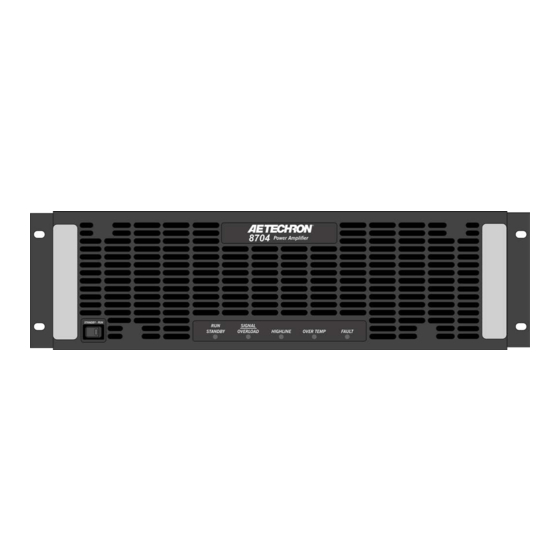
8704 OPERATOR’S MANUAL – SECTION 1 Figure 1.1 – 8704 Front Panel 1 Introduction Congratulations on your purchase of the 8704 Performance Overview digital power amplifier. 8704 amplifiers are 200Vp, low-noise, DC-to-250-kHz switch -mode amplifiers. DC - 250 kHz Bandwidth They are fast enough for DC automotive dropout testing and capable of AC voltages required for 0 to 350 VDC Voltage 0 to 250 V ISO 61000 and Aviation testing. Plus, they have low enough noise and distortion specifications to Current 60 A be the reference power source in power quality measurements. Distortion <0.2% 1.1 Features Power 4 kW Wide Bandwidth and Flexible Apparent Power 20 kVA The 8704 amplifier is capable of reproducing AC, ... -
Page 6: Amplifier Unpacking And Installation
8704 OPERATOR’S MANUAL – SECTION 2 2 Amplifier Unpacking and Installation The 8704 amplifier is a precision instrument that 2.3 Installation can be dangerous if not handled properly. Lethal The 8704 amplifiers are packaged in a rugged voltages are present in both the AC input supply powder-coated chassis. This chassis is 3U (rack and the output of the amplifier. For this reason, units) tall, and has rack “ears” on each side of the safety should be your primary concern when you front panel for mounting to a standard EIA (Elec- setup and operate this amplifier. tronic Industries Association) rack. Use standard rack mounting hardware to mount the ampli- 2.1 Safety First fier. Use nylon washers if you wish to protect the Throughout this manual special emphasis is powder-coat finish on the front of the amplifier. placed on good safety practices. The following Optionally, the amplifier can be placed on a graphics are used to highlight certain topics that bench top; please keep in mind that the protective require extra precaution. powder-coating can be scratched when placed on other equipment or on a bench top, especially WARNING when there is dirt present. To protect the finish, a set of rubber feet is included in the toolkit that can WARNING alerts you to hazards that be installed on the bottom of the amplifier. -
Page 7: Connecting The Load
8704 OPERATOR’S MANUAL – SECTION 3 Figure 3.1 – 8704 Back Panel are operating correctly. Once proper operation is Be sure to install the output safety cover after wir- confirmed, refer to the Applications section of this ing the output connections. See Figure 3.3. manual for instructions on configuring and operat- ing your amplifier in Controlled-Current mode. 3.1 Connecting the Load 3.1.1 Preparation and Cautions Before connecting the amplifier, make sure the AC power is disconnected. Always use the appropriate wire size and insula- tion for the maximum current and voltage expected at the output. Never connect the output of the amplifier to any other model amplifier, power sup- Figure 3.2 – Connecting the Load ply, signal source, or other inappropriate load; fire can result. WARNING ELECTRIC SHOCK HAZARD. -
Page 8: Other Dip Switch Settings
8704 OPERATOR’S MANUAL – SECTION 3 3.4 Monitor and Sense Ports The amplifier provides five additional back-panel ports: Current Monitor (BNC connector) • Voltage Monitor (BNC connector) • Multi-amp Connectors (9-pin dSub connectors, • two total) Remote Sense Port (2-pin terminal block con- • nector. See the Applications section of this manual for information on using these ports Figure 3.4 – Wiring for Unbalanced or Balanced WARNING Input Connector The back-panel DIP switch #1 can be used to en- The risk of lethal ELECTRICAL SHOCK able/disable the unbalanced input connector, and exists when connecting AC mains! Disconnect the source before connect- DIP switch #2 can be used to enable/disable the ... - Page 9 8704 OPERATOR’S MANUAL – SECTION 3 Do not disconnect or disable the protective grounding connection. Doing so causes a potential electrical shock hazard. Connect the AC supply to the three-terminal bar- rier strip located on the amplifier back panel (see Figure 3.6 and 3.7). Install AC inlet cover prior to connecting to the sup- ply source. See Figure 3.8. Figure 3.6 – AC Mains Barrier Strip Wiring for 230/240VAC models WARNING ELECTRIC SHOCK HAZARD. AC supply potentials can be lethal. Inlet cover must remain installed at all times to protect against HAZARDOUS LIVE VOLTAGES Start-up Procedure 1.
-
Page 10: Amplifier Operation
8704 OPERATOR’S MANUAL – SECTION 4 4 Amplifier Operation To release the amplifier from Standby mode: 1. High/Low Line error: Clear the over- or un- 4.1 Front-Panel Controls and Indicators der-voltage condition. The amplifier will resume This section provides an overview of Front-Panel operation when the input voltage is brought controls and indicators found on the 8704. Refer fo within the operating range of the amplifier. Figure 4.1 for component locations. 2. Overtemp condition: Remove the input signal 4.1.1 Standby-Run Switch from the amplifier and leave the amplifier with The Standby-Run switch controls the power to the the Standby-Run switch in the Run position amplifier’s high-voltage transformers. Switch to and with the fans operating to cool the ampli-... - Page 11 8704 OPERATOR’S MANUAL – SECTION 4 Overload (clipping): The indicator will flash when the temperature sensors detect a condition amber intermittently. When the indicator flashes that would damage the amplifier. If the Overtemp amber, this indicates that the output of the system pulse is extremely short, as in the case of defec- could not follow the input signal due to voltage tive wiring or switches, this indicator may be lit too or current limits. The amber Overload indicator briefly to observe. will begin flashing when distortion is greater than To remove the amplifier from Standby and return 0.1%. it to normal operation after an Overtemp fault has occurred, make sure the Standby-Run switch 4.1.4 High/Low Line Indicator is in the Run position and the amplifier fans are This amber indicator will illuminate, and the ampli- running, and then remove the input signal from fier will be placed in Standby if the detected AC the amplifier. Allow the fans to run until the ampli- mains voltage is outside of the operable range of fier automatically returns to Run mode. See the the amplifier (±10%). This can occur if the ampli- Troubleshooting section for information on iden- fier’s back-panel breaker is not in the on position tifying and correcting the cause of an Overtemp (left), or if the AC supply into the amplifier is higher or lower than the operable range. ...
-
Page 12: Back-Panel Controls & Connectors
8704 OPERATOR’S MANUAL – SECTION 4 Remote Sense Port – This 2-pin terminal block Back-Panel Controls & Connectors connector provides a sense line for voltage correc- This section provides an overview of Back-Panel tion. The Remote Sense port can be useful when controls and connectors found on the 8704. Please the voltage at the load must be precise. If the refer to Figure 4.2 for component locations. cables connecting the amplifier and the load are very long or under-sized, the voltage drop between AC Power Input – Three-terminal barrier strip the amplifier and load can be corrected. connector. Connect to the Remote Sense Port using high- Breaker– Protects the amplifier from voltage surge quality shielded wire and the supplied terminal on the AC power input. block connector. Connect the shield to a 1/4-inch Output Terminals – Connect output lines from the ring terminal, then secure to the grounding screw load to this pair of high-current output terminals ... -
Page 13: Advanced Configuration
Select and enable a synthetic impedance from • Select between two compensation networks for • 0.125 ohms to 0.875 ohms. Controlled Current operation: CC1, designed 8704 Default DIP Switch Settings Red = Default DIP SWITCH SETTINGS DOWN 1 UNBALANCED INPUT 2 BALANCED INPUT 3 DC SERVO 4 OPERATION MODE 5 COMPENSATION NETWORK 2... -
Page 14: Dip Switch Configurations
8704 OPERATOR’S MANUAL – SECTION 5 5.1 DIP Switch Configurations CAUTION The 8704 amplifier provides 24 DIP switches locat- ed on the amplifier back panel. Most configuration In Controlled-Current Mode, the load is part of the amplifier settings can be made using these DIP switches. circuit, and the relationship of the load to the amplifier is critical. For proper and safe operation in Controlled-Current See Figure 5.1 for default DIP switch settings and mode, you must obverve the following guidelines: descriptions. 1. Properly attach a load before operating the amplifier. SW#1: Unbalanced Input 2. DO NOT use a blocking capacitor. The load must have a DC path. - Page 15 8704 OPERATOR’S MANUAL – SECTION 5 tion and load, the Compensation Network 1 switch please contact AE Techron Technical Support. can be turned off and the Compensation Network SW#7: Control Configuration 2 switch can be used to enable a network that pro- When this switch is in the UP position (default), the vides 100k ohm resistance and 10 nF capacitance amplifier will function as a stand-alone amplifier or as and should be used with loads that are 500 μH to a Master amplifier in a multi-amp system. When this 1.5 mH. switch is in the DOWN position, the amplifier will func- NOTE: It is recommended to only use one of the tion as a Follower amplifier in a multi-amp system. compensation networks at a time. Having SW#5 For more information on multi-amplifier system and SW#6 both on (UP) will likely provide improper configuration and operation, see the Applications compensation for the load, and may result in ampli- section. fier instability. SW#8: Coupling For more information on Controlled-Current opera- When the Coupling DIP switch is in the UP posi- tion, including instructions for selecting the best ...
-
Page 16: Custom Compensation
8704 OPERATOR’S MANUAL – SECTION 5 ON = DIP Switch UP OFF = DIP Switch DOWN ON = DIP Switch UP OFF = DIP Switch DOWN Synthetic Current SW#18 SW#19 SW#20 Impedance SW#21 SW#22 SW#23 SW#24 Limit 0.875Ω 160A 0.750Ω 150A 0.625Ω 140A 0.500Ω 130A 0.375Ω 120A 0.250Ω 110A 0.125Ω 100A 0.00Ω Figure 5.2 – Synthetic Impedance Switch Configurations abled. When this switch is in the UP position, Gain Matching is enabled. SW#18 - SW#20: Synthetic Impedance These three switches allow the addition of a synthetic impedance on the output of the ampli-... -
Page 17: Applications
8704 OPERATOR’S MANUAL – SECTION 6 6.2 Controlled-Voltage vs. Controlled- 6 Applications Current Modes of Operation 6.1 Emergency Standby Switch or AE Techron 8704 amplifiers can be field-configured Safety Interlock to operate as Voltage Amplifiers (Voltage-Con- The two 9-pin D-Sub connectors on the amplifier trolled Voltage Source) or as Transconductance back panel (Interlock A and Interlock B) can be Amplifiers (Voltage-Controlled Current Source). used to remotely place the amplifier in Standby The mode selection is made via the back-panel mode. This can provide a valuable safety feature, DIP switch #4. See the Advanced Configuration such as in creating a safety interlock for a cabinet section for more information. in which one or more 8704 amplifiers are installed When configured as a Controlled-Voltage source or wiring an emergency stop switch to the cabinet (voltage amplifier), the amplifier will provide an ... - Page 18 8704 OPERATOR’S MANUAL – SECTION 6 When operating in Controlled-Current (CC) mode, a compensation circuit is required to ensure ac- curate output current. Since the load is a critical circuit component in CC mode, the inductive and resistive values of the load will determine the re- quired compensation values. One of the two compensation settings that can be enabled with DIP switch settings will be sufficient Figure 6.3 – Input to Output Comparison, for most applications. If you determine that neither Controlled-Current Operation Compensation Network 1 or Compensation Net- work 2 will be adequate for your application and 6.2.1 Safety and Operation Consider- load, please contact AE Techron Technical Sup- ations for Controlled Current Operation port for additional compensation options. When an AE Techron amplifier is configured as a Controlled-Current source, care needs to be ...
- Page 19 8704 OPERATOR’S MANUAL – SECTION 6 STEP 2: Determine Required Compensation. NOTE: Load Resistance (R) is assumed to be When operating an amplifier in Controlled- Current mode, the load becomes an integral part <5 ohms. of the system. In order to determine the required Load Compensation Compensation compensation for your load, consulting the follow- Network Inductance (L) Capacitance (CC) ing table to determine the approximate compen- 75 µH to 1 mH 0.0022 µF Network 1 sation capacitance (CC) required based on the 1 mH to 5 mH inductance of your load. Note that these calcula- 0.0100 µF...
-
Page 20: Driving Reactive Loads
For routine, Controlled-Voltage applications, fier’s power supply. This allow the amplifier to Parallel and Push/Pull amplifier systems can be deliver continuous apparent power that is up to five configured using standard 8704 amplifiers and the times the rated power of the amplifier when driving following accessory available from AE Techron: reactive loads. 8000 Series Multiamp Kit (part number 69- 6.4 8704 Multi-amp Systems 8005462). The 8704 amplifier may be used with one other Please contact AE Techron’s Sales Department 8704 amplifier in either a Parallel or a Push/Pull for more information. (Series) configuration. The Parallel configuration CONFIGURATION CONTINUOUS OUTPUT will approximately double the continuous current (100% Duty Cycle) output to 120 Arms, while the Push/Pull configura- Two 8704 in Parallel 250 Vrms / 120 Arms Configuration tion will approximately double the voltage avail-... - Page 21 8704 Follower DIP Switch Settings Parallel Configuration 1 2 3 4 5 6 7 8 9 10 11 12 13 14 15 16 17 18 19 20 21 22 23 24 KEY FOR DIP SWITCH SETTINGS:...
- Page 22 8704 OPERATOR’S MANUAL – SECTION 6 2. Place the Follower amplifier on top of the tion of at least three digits. Both testing methods Master amplifier, and then connect the bus are provided below. bar (from the 8704 Multi-amp Kit) between the Testing Using an Oscilloscope GND output terminals of the Master and Fol- 1. Connect from a signal generator to the BNC or lower amplifiers. See Figure 6.8. WECO signal input connector on the back panel A. Remove the back-panel output covers from of the Master amplifier. Note that if the WECO both amplifiers. connector is used for signal input, DIP switch #1 B. Remove the 3/8-inch nuts from the GND on the Master amplifier should be placed in the terminals on both amplifiers. DOWN (OFF) position and DIP switch #2 should C. Install the bus bar across the GND termi- be placed in the UP (ON) position. nals of the Master and Follower amplifiers. 2. Turn down the level of your signal source. D. Replace the 3/8-inch nuts on both output 3. Make sure the back panel breaker switch on terminals. IMPORTANT: Torque the nuts both amplifiers is in the ON position, and then ...
- Page 23 8704 OPERATOR’S MANUAL – SECTION 6 7. Check the accuracy between the oscilloscope at or very near to 100 Vrms. Record the mea- channels by connecting channel two of the sured output. oscilloscope between the Master amplifier’s 8. Set your multimeter to measure AC volts RMS Output connector and the GND bus bar. The at a low scale, then connect between the Mas- measured output should be the same as the ter Output connector and the Follower Output output recorded on channel one. connector. The measured output should be 8. Move the channel two probes to connect be- less than 0.5V. tween the Follower amplifier’s Output connec- IMPORTANT: If the difference in output be- tor and the GND bus bar. tween the two outputs is greater than 0.5V, DO 9. Observe the measured output on the two chan- NOT complete the system setup.
- Page 24 8704 OPERATOR’S MANUAL – SECTION 6 TWO 8704 AMPLIFIERS PARALLELED (CRITICAL WIRE LENGTHS) OUTPUT OUTPUT AMP #2 FOLLOWER OUTPUT OUTPUT AMP #1 MASTER Both wires of length “A” should be of the same length ±1/4 inch. Ÿ Wire lengths “A” and “B” may or may not be of the same length.
- Page 25 Consider placing a “Master” or “Follower” label on 8704 PARALLEL SYSTEM 8704 AMPLIFIERS 8704 AMP #2 - FOLLOWER 1 2 3 4 5 6 7 8 9 10 11 12 13 14 15 16 17 18 19 20 21 22 23 24 AMPLIFIER OUTPUTS OUTPUT 8704 AMP #1 - MASTER...
- Page 26 8704 OPERATOR’S MANUAL – SECTION 6 8704 Follower DIP Switch Settings Push/Pull Configuration 1 2 3 4 5 6 7 8 9 10 11 12 13 14 15 16 17 18 19 20 21 22 23 24 KEY FOR DIP SWITCH SETTINGS: 8704 Master DIP Switch Settings REQUIRED Push/Pull Configuration...
- Page 27 8704 OPERATOR’S MANUAL – SECTION 6 8704 PUSH/PULL SYSTEM 8704 AMPLIFIERS 8704 AMP #2 - FOLLOWER 1 2 3 4 5 6 7 8 9 10 11 12 13 14 15 16 17 18 19 20 21 22 23 24 AMPLIFIER OUTPUTS OUTPUT 8704 AMP #1 - MASTER...
- Page 28 8704 OPERATOR’S MANUAL – SECTION 6 amplifiers will return automatically to Run mode. to determine the current status and the necessary remedies to return the system to operational status If the High/Low-Line indicator does not turn off or if the system does not return from Standby, one when a fault condition occurs. or both amplifiers may require servicing. See the Run/Standby Indicators Troubleshooting section in this manual for more When each amplifier in a multi-amp system is information. energized, the amplifier will be placed in Standby mode (Run/Standby LED solid amber) and remain Overtemp: Both amplifiers monitors the tempera- ture inside its high-voltage transformers and in in Standby mode until both amplifiers in the system the output stage heat sinks. The amber Overtemp have been energized. The system will automati- indicator will light and the system will be placed cally proceed to Run mode when both amplifiers in Standby mode when the temperature sensors ...
-
Page 29: Maintenance
8704 OPERATOR’S MANUAL – SECTION 7 To ensure adequate cooling and maximum ef- 7 Maintenance ficiency of the internal cooling fans, the amplifier’s Simple maintenance can be performed by the user front and rear grills should be cleaned periodically. to help keep the equipment operational. The fol- To clean the amplifier grills and filter, complete the lowing routine maintenance is designed to prevent following steps: problems before they occur. See the Trouble- 1. Disconnect the amplifier from its power source shooting section, for recommendations for re- via external mechanical disconnect or breaker. storing the equipment to operation after an error 2. The front grill is secured to the amplifier front condition has occurred. panel by magnets. Pull out on the grill to re- Preventative maintenance is recommended after lease it from the front panel. the first 250 hours of operation, and every three 3. Remove the filter located behind the front grill. months or 250 hours thereafter. If the equipment 4. Using a vacuum cleaner, vacuum the front ven- environment is dirty or dusty, preventative mainte- tilation grill, the grill filter, and the back ventila- nance should be performed more frequently. tion exit grill. ... -
Page 30: Troubleshooting
8704 OPERATOR’S MANUAL – SECTION 8 8 Troubleshooting First, check to make sure the amplifier’s back- panel breaker is turned on. Next, check the voltage 8.1 Introduction & Precautions level of the AC supply. If the AC mains voltage is more than 10% outside the range of the operating This section provides a set of procedures for voltage, increase or reduce the AC mains voltage identifying and correcting problems with the 8704 to the proper level. When the line voltage condition amplifier. Rather than providing an exhaustive and is corrected, the amplifier will automatically return detailed list of troubleshooting specifications, this to Run mode. If the amplifier does not reset, the section aims to provide a set of shortcuts intended amplifier’s internal transformers may need to be to get an inoperative amplifier back in service as replaced. Please see the Factory Service infor- quickly as possible. mation at the end of this section. The procedures outlined in this section are direct- ed toward an experienced electronic technician; 8.5 Run/Standby LED Remains Amber it assumes that the technician has knowledge of ... -
Page 31: Fault Led Is Illuminated
8704 OPERATOR’S MANUAL – SECTION 8 3. Undesired DC offset at the Output and Input signal. 1. Turn off the signal source. 2. Turn off the AC mains. If the amplifier chronically overheats with suitable 3. Turn AC mains power back on. If the Fault LED power/load conditions, then the amplifier may not doesn’t illuminate again, press the Standby- be receiving adequate airflow. To check for ad- Run switch to place the amplifier in Run mode equate airflow, proceed with the following steps: and turn the signal source on. 8.6.2 Check for Inadequate Airflow 4. If the Fault LED is still illuminated and the Fault 1. Check air filters. Over time they can become condition doesn’t clear, return the amplifier for dirty and worn out. It is a good idea to clean Factory Service. See the Factory Service infor- the air filters periodically with a mild detergent mation at the end of this section. - Page 32 8704 OPERATOR’S MANUAL – SECTION 8 Appendix A: Gain DIP Switch Settings Use this chart to determine the required settings switches ON = Gain of 39.85, all switches OFF = for DIP switches 9 through 16 to achieve the am- gain of 0 (signal will not be amplified). plifier gain you need for your application. Note: All ON = DIP Switch UP OFF = DIP Switch DOWN SW#9 SW#10 SW#11 SW#12 SW#13 SW#14 SW#15 SW#16 Gain 39.85 39.69 39.54 39.38 39.22 39.06 38.91 38.75 38.60 38.44 38.29 38.13 37.97 37.81 37.66 37.50 37.35 37.19 37.04...
- Page 33 8704 OPERATOR’S MANUAL – SECTION 8 ON = DIP Switch UP OFF = DIP Switch DOWN SW#9 SW#10 SW#11 SW#12 SW#13 SW#14 SW#15 SW#16 Gain 33.29 33.13 32.97 32.81 32.66 32.50 32.35 32.19 32.04 31.88 31.72 31.56 31.41 31.25 31.10 30.94 30.79 30.63 30.47 30.31 30.16 30.00 29.85 29.69 29.54 29.38 29.22 29.06 28.91 28.75...
- Page 34 8704 OPERATOR’S MANUAL – SECTION 8 ON = DIP Switch UP OFF = DIP Switch DOWN SW#9 SW#10 SW#11 SW#12 SW#13 SW#14 SW#15 SW#16 Gain 25.63 25.47 25.31 25.16 25.00 24.85 24.69 24.54 24.38 24.22 24.06 23.91 23.75 23.60 23.44 23.29 23.13 22.97 22.81 22.66 22.50 22.35 22.19 22.04 21.88 21.72 21.56 21.41 21.25 21.10...
- Page 35 8704 OPERATOR’S MANUAL – SECTION 8 ON = DIP Switch UP OFF = DIP Switch DOWN SW#9 SW#10 SW#11 SW#12 SW#13 SW#14 SW#15 SW#16 Gain 17.97 17.81 17.66 17.50 17.35 17.19 17.04 16.88 16.72 16.56 16.41 16.25 16.10 15.94 15.79 15.63 15.47 15.31 15.16 15.00 14.85 14.69 14.54 14.38 14.22 14.06 13.91 13.75 13.60 13.44...
- Page 36 8704 OPERATOR’S MANUAL – SECTION 8 ON = DIP Switch UP OFF = DIP Switch DOWN SW#9 SW#10 SW#11 SW#12 SW#13 SW#14 SW#15 SW#16 Gain 10.31 10.16 10.00 9.85 9.69 9.54 9.38 9.22 9.06 8.91 8.75 8.60 8.44 8.29 8.13 7.97 7.81 7.66 7.50 7.35 7.19 7.04 6.88 6.72 6.56 6.41 6.25 6.10 5.94 5.79...
- Page 37 8704 OPERATOR’S MANUAL – SECTION 8 ON = DIP Switch UP OFF = DIP Switch DOWN SW#9 SW#10 SW#11 SW#12 SW#13 SW#14 SW#15 SW#16 Gain 2.66 2.50 2.35 2.19 2.04 1.88 1.72 1.56 1.41 1.25 1.10 0.94 0.79 0.63 0.47 0.31 0.16 Information subject to change 96-8006282_03-11-2022...
Need help?
Do you have a question about the 8704 and is the answer not in the manual?
Questions and answers