
Related Manuals for Aetechron 7224


Summary of Contents for Aetechron 7224
- Page 1 7224 Operator’s Manual Single-Channel Industrial Amplifier for Demanding, High-Power Systems 574.295.9495 | www.aetechron.com 2507 Warren Street, Elkhart, IN 46516...
- Page 2 This Declaration of Conformity is issued under the sole responsibility of AE Techron, Inc., and belongs to the following product: Equipment Type: Industrial Power Amplifiers Model Name: 7224 EMC Standards: EN 61326-1: 2013 – Electrical Equipment for Measurement, Control and Laboratory use —...
- Page 3 2507 Warren St. Elkhart, IN, 46516, U.S.A. receive an authorization to return the product for (574) 295-9495 service. All components must be shipped in a factory www.aetechron.com pack or equivalent which, if needed, may be obtained...
-
Page 4: Table Of Contents
Contents 1 Introduction ............................5 1.1 Features ..........................5 1.2 Configuration Options......................5 2 How to Use this Manual .........................6 2.1 Determine Your Amplifier Version ..................6 2.2 Safety First ..........................7 3 Amplifier Unpacking and Installation ....................8 3.1 Unpacking ..........................8 3.2 Installation ..........................8 4 Connections and Startup .......................9 4.1 Other Operation Modes and Configurations................9 4.2 Connecting the Load ......................9 4.3 ... -
Page 5: Introduction
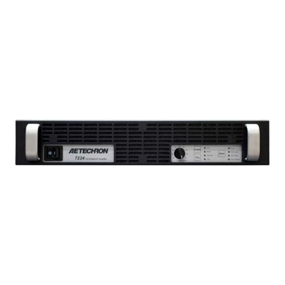
7224 OPERATOR’S MANUAL – SECTION 1 Figure 1.1 – 7224 Front Panel 1 Introduction Performance Overview* Congratulations on your purchase of the 7224 AE Techron power amplifier—one of the most precise Small Signal Bandwidth (8V p-p) DC - 600 kHz power amplifiers ever produced for industrial ap- plications and testing. The 7224 amplifier is built Max Continuous Power, 20 kHz 900 watts RMS and tested to the most stringent quality standards For High-Power Applications to: 100 kHz for long life and outstanding performance. The AE Techron brand is known throughout the world for DC Power: 16A at 13.5 VDC its robust precision amplifiers as well as its product ... -
Page 6: How To Use This Manual
7224 OPERATOR’S MANUAL – SECTION 2 2 How to Use this Manual 2.1 Determine Your Amplifier Version Version C has external DIP switches on the This manual contains setup and operating informa- amplifier’s back panel, but does not have the two tion for several versions of the 7224 amplifier. DB9 ports. It is configured using the external DIP Version A is a 7224 amplifier with a serial num- swiches. ber ending in -2785 or lower. Version A units with Version D has both external DIP switches and the a serial number ending in -2628 and lower have two DB9 ports on the back panel. It is configured a removable access panel in the amplifier’s top using the external DIP swiches. cover. The amplifier does not have external DIP switches or the two DB9 ports on the back panel. It See Figures 2.1 and 2.2 for assistance in identify- is configured using jumpers located on the ampli-... -
Page 7: Safety First
7224 OPERATOR’S MANUAL – SECTION 2 VERSION B Units with internal DIP switches. Remove the top cover to access the DIP switches. VERSION C Units with external DIP switches (on amplifier back panel). VERSION D Units with external DIP switches (on amplifier back panel). The amplifier also provides two DB9 Interconnect connectors on the amplifier back panel. -
Page 8: Amplifier Unpacking And Installation
Power Cord • 7224 Operator’s Manual and Quick Start sheet • CAUTION Do not operate the amplifier in a small sealed chamber of any kind. Improper operations and overheating will result. * The earliest version of the 7224 has an aluminum chassis. Information subject to change 96-8006348_05-31-2022... -
Page 9: Connections And Startup
7224 OPERATOR’S MANUAL – SECTION 4 Figure 4.1 – 7224 Back Panel (Version D shown) 4 Connections and Startup first be wired and tested individually in Controlled- This section details the wiring and startup pro- Voltage mode to ensure proper operation. cedures for a single 7224 amplifier operating in Controlled-Voltage mode (factory default). Before For Series or Push/Pull operation in Controlled- connecting the amplifier, make sure the AC power Voltage mode, refer to the topic “Multiamp Sys- cord is unplugged. tems for Increased Current or Voltage” in the Ap- plications section of this manual for information WARNING on Series and Push/Pull system configuration. ELECTRIC SHOCK HAZARD. For Series or Push/Pull operation in Controlled- Output potentials can be lethal. -
Page 10: Connecting The Input Signal
7224 OPERATOR’S MANUAL – SECTION 4 Always use the appropriate wire size and insula- card can easily be removed and replaced with tion for the maximum current and voltage expected alternate SIM cards designed for special applica- at the output. Never connect the output of the tions, when required. amplifier to any other model amplifier, power sup- The SIM BNC card provides both an unbalanced ply, signal source, or other inappropriate load; fire Input BNC jack and a balanced Input “WECO” can result. terminal block connector. (Mating connector for the WECO connector is provided.) Connect your input WARNING signal to the unbalanced or balanced input con- nector as shown in Figure 4.3. Use cables that are ELECTRIC SHOCK HAZARD. high quality and shielded to minimize noise and to Output potentials can be lethal. Make guard against possible feedback. connections only with AC Power OFF and input signals removed. -
Page 11: Other Back Panel Controls And Connectors
7224 OPERATOR’S MANUAL – SECTION 4 connecting multiple amps in push/pull or parallel configurations. See the Applications section of this manual for more information. INTERLOCK I/O CONNECTOR: The Interlock Connector can be used to provide remote control and monitoring of the amplifier, and for connecting amps in multiamp configurations. See the Applica- tions section of this manual for information. 4.5 Connecting the AC Supply The power cord connects to a standard 20A 3-pin IEC-type male connector on the back panel (see Figure 4.5). Make sure the Breaker/Switch on the front panel is switched to the OFF (O) position. Figure 4.4 – Input Select Switch Settings for Unbalanced or Balanced Input Connectors Make sure the power cord is inserted and seated fully into the IEC connector by moving it slightly ... -
Page 12: Amplifier Operation
7224 OPERATOR’S MANUAL – SECTION 5 5 Amplifier Operation 5.1 Front-Panel Controls This section provides an overview of Front-Panel controls and indicators found on the 7224. 5.1.1 Power Switch The Power Switch controls the AC mains power to the amplifier. Switch to the ON position (|) to turn Figure 5.1 – Power Switch the amplifier on. Switch to the OFF position (O) to turn the amplifier off. See Figure 5.1. The Power Switch also serves as a Breaker. When the Breaker is tripped, the Power Switch moves to a neutral position between ON and OFF. To reset the Breaker, turn the amplifier OFF (O) and then turn it back ON (I). Figure 5.2 – Gain Control 5.1.2 Gain Control factory-default setting and configure the amplifier The Gain Control Knob increases/decreases the to power-up in Standby/Stop mode, please see the gain from 0 – 100% of the overall Gain. Turn the Advanced Configuration section. -
Page 13: Front-Panel Indicators
7224 OPERATOR’S MANUAL – SECTION 5 If an amplifier is disabled using a Remote Standby dition has been cleared and the amplifier has been switch, the amplifier will be placed in Remote configured for startup in Run mode. If the amplifier Standby mode. To return the amplifier to a Run has been configured for startup in Standby/Stop condition, release the Standby condition using the mode, pressing the Reset button will place the remote switch. See the Applications section of amplifier in Standby/Stop mode. Press the Enable this manual for more information on remote ampli- button to return the amplifier to Run mode. fier operation. 5.2 Front-Panel Indicators Standby/Fault mode (Standby and one or more 5.2.1 Main Status Indicators Fault LEDs lit): The amplifier has been placed in Four Main Status indicators are located on the am- Standby due to an Output, Overload, Over Temp ... - Page 14 7224 OPERATOR’S MANUAL – SECTION 5 Figure 5.5 – Main Status Indicators Indicator is lit Indicator is not lit Indicator may be lit Main Status Indicators State of Operation Action Needed to Return to Run Mode Run mode: The amplifier’s high-voltage transformers are energized and the unit will amplify the input signal. Run mode is initiated Ready by: (1) the Enable push button, or (2) when Standby the amplifier powers up in Run mode (factory Stop default). See the Advanced Configuration...
- Page 15 7224 OPERATOR’S MANUAL – SECTION 5 Figure 5.6 – Fault Status Indicators Indicator is lit Indicator is not lit Indicator may be lit Action Needed to Clear Fault Main Status Fault Status Condition and Return to Indicators Indicators State of Operation Run Mode Output Fault status: This indicates This fault condition cannot be cleared that an Output Fault condition has oc-...
-
Page 16: Back-Panel Controls And Connectors
7224 OPERATOR’S MANUAL – SECTION 5 Back-Panel Controls CAUTION and Connectors This section provides an overview of Back-Panel Turn the amplifier OFF before chang- controls and connectors found on the 7224. Please ing DIP switch positions. Some switch changes could result in amplifier damage. refer to Figure 5.7 for visual locations. AC Supply – Standard 20 amp 3-pin IEC-type DIP Switches* (Versions B, C and D only): The eight back-panel DIP switches can be used to en-... -
Page 17: Advanced Configuration
Version A main board configuration instructions. for DIP switch settings and descriptions. CAUTION *These features not available on Version A 7224 amplifiers. The gain on Version A amplifiers may be configured as vari- able (default) or fixed, but the 6:1 gain setting is not available. Turn the amplifier OFF before chang- **DIP switches are not available on Version A. - Page 18 SW#6: Master/Follower* of a 68.1 kΩ resistor in series with a 47 nF capaci- When the Master/Follower DIP switch is in the Up tor. Place the DIP switch in the Down position to position (default), the amplifier will function as a select CC2 network. This network is unpopulated, stand-alone amplifier or as a Master amplifier in but can be populated with a custom compensation a multi-amp system. When this switch is in the Down position, the amplifier will function as a Fol- *On Version A 7224 amplifier, this function is configured on lower amplifier in a multi-amp system. the amplifier main board. See Appendix B for more informa- tion. Information subject to change 96-8006348_05-31-2022...
-
Page 19: Internal Configurations
7224 OPERATOR’S MANUAL – SECTION 6 For more information on multi-amplifier system Main Board (Versions B, C and D only): configuration and operation, see the Applications Install a custom compensation network for use • in Controlled-Current operation, section. Configure the amplifier to operate with a fixed SW#7: Voltage Input (Low/High) • gain instead of the default variable gain, When the Voltage Input DIP switch is in the Up Configure the amplifier to enter Standby on position (default), the voltage input is set to line • startup instead of entering Run mode (default) level and the amplifier can be configured for use Configure the amplifier to enter Standby when in a Parallel or Push/Pull multi-amp system. When • an Overload fault condition occurs. this switch is in the Down position, voltage input is set to high, and the amplifier can be configured for Power Supply Board (All Versions): use in a Series multi-amp system. ... - Page 20 #2 Phillips screwdriver tion” in the Applications section of this manual. Procedure Enable/Stop on Power-up 1. Remove power from the amplifier and discon- The 7224 amplifier will power-up to Run Mode nect any load from the amplifier outputs. Wait a when a shunt is placed across pins 1 and 2 on the minimum of three minutes to allow the ampli- Enable/Stop jumper (default setting). See Figure fier’s capacitors to discharge. 6.3. To cause the 7224 amplifier to enter Standby 2. Remove the amplifier’s front grill cover by (Stop Mode) on power-up, place the shunt across firmly pulling the grill cover away from the front pins 2 and 3. panel. The grill is held by magnets. 3. Use the Phillips screwdriver to remove nine (9) screws: a. Three (3) screws from each side b. One (1) screw from the back c. Two (2) screws from the front (after the grill cover is removed.
- Page 21 7224 OPERATOR’S MANUAL – SECTION 6 Fixed or Variable Gain The 7224 amplifier ships with an enabled Gain forms observed at the amplifier input and output. Control knob, which is located on the amplifier When a distortion between the two waveforms front panel. To disable the Variable Gain control of more than 0.5% occurs, the IOC circuit will and set for a Fixed Gain, locate the Gain Control activate, and the Overload LED will light, but the Bypass jumper, remove the gain control wire, and amplifier will continue to operate. To configure the place a shunt across the two pins at that location. 7224 to move to Standby (Fault mode) when the See Figure 6.4. IOC circuit is activated, locate the Overload Latch (see Figure 6.5) and place a shunt across the two Standby on Overload pins of the jumper. The 7224’s IOC (Input/Output Comparator) Distor- tion Alert circuit continuously compares the wave- Figure 6.4 – Configure for Fixed or Variable Gain Figure 6.5 – Configure for Standby (Fault Mode) on Overload Information subject to change...
- Page 22 7224 OPERATOR’S MANUAL – SECTION 6 6.2.3 Configuration Settings Located on During normal operation, the 7224 will use the the Power Supply Board (All Versions) signal received at input to calculate the expected voltage requirements of the application. When The following custom settings are configured on voltages higher than 90V are required, the trans- the Power Supply Board: formers will automatically be switched to a series Amplifier Voltage Potential setting (high current • configuration to provide up to 180V output. or high voltage) Bi-Level Power Supply setting When the 7224 senses that the voltage required • has dropped below the 90V limit, the transformers Power Supply Settings for Increased will automatically be returned to a parallel configu- Voltage or Current ration, reducing heat output and increasing operat-...
- Page 23 7224 OPERATOR’S MANUAL – SECTION 6 LOAD (ohms) BI-LEVEL POWER SUPPLY OUTPUT RECOMMENDED VOLTAGE RAILS APPLICATIONS Continuous Pulse SWITCH High current operation 0.5 - 1 0.25 - 0.75 Mid-level operation 45-90 2 - 4 1 - 2 Auto High Not recommended Fastest rise to >45V; <90V 2 - 4 1 - 2 High voltage operation...
- Page 24 7224 OPERATOR’S MANUAL – SECTION 6 Figure 6.9 – Location of Amplifier High-Voltage Figure 6.10 – J3 and J7 Plug Locations for High-Current Output Transformer Sockets Figure 6.11 – J4 and J8 Plug Locations for High-Voltage Output To access and change the Bi-Level Power Switch, 5. Move the black switch to the desired setting. If follow these steps: necessary, use a pointed, non-metallic object (such as a pen) to help in moving the switch. 1. Locate the SIM Input Card on the right side of the rear panel of the amplifier. a. Automatic – Left 2. Using a #2 Phillips screwdriver, remove the two screws located at the edges of the SIM card. b. Low – Middle 3. Keeping the ribbon cable attached, remove the c. High – Right SIM card from the amplifier until it is completely clear from the card bay. 4. Locate the Bi-Level Power Switch, S1, a black, three-position switch at the rear of the card ...
-
Page 25: Applications
7224 OPERATOR’S MANUAL – SECTION 7 7 Applications Remote Enable/Standby The procedures outlined in this section assume • Temperature monitor competence on the part of the reader in terms of • amplifier systems, electronic components, and • Current monitor Voltage monitor good electronic safety and working practices. • Figure 7.1 maps the pins used for these applica- 7.1 Remote Status and Control using tions. NOTE: Both 9-pin D-Sub connectors have the the Interconnect Ports (Version D same pin-outs and either port can be used for remote only) applications. AE Techron 7224 amplifiers come with two back- panel female 9-pin D-Sub connectors that can be used to provide remote control and monitoring of the amplifier. The information provided here will instruct you in the wiring of several control and status applica- Figure 7.1 – Remote Status and Control Pin-outs ... - Page 26 7224 OPERATOR’S MANUAL – SECTION 7 7.1.2 Remote Monitoring of Temperature Using one of the 9-pin D-Sub connectors located on the back panel of the amplifier, you can remote- ly monitor the temperature at the heat-sinks of the amplifier. Remote Monitoring of Temperature Purpose: Use a voltage meter to monitor tempera- ture at the heat-sinks. Method: Connect a voltage meter to monitor the temperature at the heatsinks of the amplifier. Con- nect across Temp (PIN 4) and Ground (PIN 3 or 6). See Figure 7.3. Figure 7.3 – Remote Temperature Monitor Signal Type: AC Level: (VDC X 100) - 273 = degrees Celsius Most digital multimeters have an input impedance IMPORTANT: This circuit has a 1K build-out resis- of 1 megohm and would work well for this applica- tor. Make sure the monitor function has sufficient impedance to avoid accidentally influencing status. ...
-
Page 27: Remote Status And Control Using The Sim Interlock I/O Connector (All Versions)
7224 OPERATOR’S MANUAL – SECTION 7 7.2 Remote Status and Control using the SIM Interlock I/O Connector (All Versions) D-Sub connector. This connector can be used to provide remote control and monitoring of the AE Techron 7224 amplifiers come with a SIM-BNC amplifier. input module that also contains a female, 25-pin The information provided here will instruct you in the wiring of several control and status applica- tions including: Run/Standby status • Amplifier status: Run, Over-temperature, Over- • load, Overvoltage; and Reset after Overload error Remote Enable/Standby • • Current monitor Temperature monitor •... - Page 28 7224 OPERATOR’S MANUAL – SECTION 7 7.2.2 Remote Amplifier Status & Reset of the amplifier when it is forced to Standby due to The SIM Interlock I/O Connector can be used to Over-load conditions. create a circuit to monitor remotely one or more Use a male, 25-pin D-Sub connector and high- amplifier conditions, including Run status, Over- quality wire to build the circuit. Figure 7.8 sche- temperature, Overload and Overvoltage. The cir- matic details the circuit and components required cuit can also be constructed to allow remote reset for all status and reset functions.
- Page 29 7224 OPERATOR’S MANUAL – SECTION 7 Remote Signal of OverVoltage Condition Remote Signal of Run Condition Purpose: LED, when lit, signals Run state. Purpose: LED, when lit, signals Overvoltage condition. Method: Use a 6mA series resistor of 4.02K-ohm Method: Use a 6mA series resistor of 4.02K-ohm for LED or OPTO, tie Run (PIN 12) to –24V source for LED or OPTO, tie OverVoltage Out (PIN 24) to (PIN 13). –24V source (PIN 13). Signal Type: DC Signal Type: DC Level when Asserted: –24V Level when Asserted: –24V Level when Deasserted: 0V...
- Page 30 7224 OPERATOR’S MANUAL – SECTION 7 When Interlock (PIN 4) is shorted to Digital Ground IMPORTANT: The amplifier must be configured for (PIN 17), amplifier is placed in Standby mode. Ready mode at startup (factory default) or the Run When switch is open, amplifier is released to the button must be pressed at the amplifier front panel at startup. The Remote Enable/Standby circuit will Run condition. Signal Type: DC not function if the Startup to Standby Latch has Level when Asserted: 0 to 8 V been activated on the amplifier. Level when Deasserted: 10 to 15 V 7.2.4 Remote Monitoring of Current Using the SIM-BNC Interlock connector located on the back panel of the amplifier, you can remotely monitor current output. Remote Monitoring of Current Output Purpose: Use a voltage meter to monitor output current.
- Page 31 7224 OPERATOR’S MANUAL – SECTION 7 7.2.5 Remote Monitoring of Tempera- ture Using the SIM-BNC Interlock connector located on the back panel of the amplifier, you can remotely monitor the temperature at the heat-sinks of the amplifier. Remote Monitoring of Temperature Purpose: Use a voltage meter to monitor temper- ature at the heat-sinks. Method: Connect a voltage meter to monitor the temperature at the heatsinks of the amplifier. Con- nect across PIN 9 (TEMP MONITOR) and PIN 10 (Sampled Common). See Figure 7.12. Signal Type: DC Level: (VDC * 100) - 273 = degrees Celsius IMPORTANT: This circuit has a 1K build-out resis- tor. Make sure the monitor function has sufficient Figure 7.12 – Remote Monitoring of Temperature impedance to avoid accidentally influencing status. Most digital multimeters have an input impedance of 1 megohm and would work well for this applica- tion.
-
Page 32: Controlled Current Operation
7224 OPERATOR’S MANUAL – SECTION 7 7.3 Controlled Current Operation The procedures outlined in this section assume competence on the part of the reader in terms of amplifier systems, electronic components, and good electronic safety and working practices. 7.3.1 Controlled-Voltage vs. Controlled- Current Modes of Operation AE Techron 7224 amplifiers can be field-configured to operate as Voltage Amplifiers (Voltage-Con- Figure 7.14 – Input to Output Comparison, trolled Voltage Source) or as Transconductance Controlled-Voltage Operation Amplifiers (Voltage-Controlled Current Source). The mode selection is made via a DIP switch on the amplifier’s back panel. See the Advanced Configuration section for more information. When configured as a Controlled-Voltage source (voltage amplifier), the amplifier will provide an output voltage that is constant and proportional to the control (input) voltage. If the load’s imped- ance changes, the amplifier will seek to maintain this ratio of input to output voltage by increasing or Figure 7.15 – Input to Output Comparison, decreasing the current it produces, as long as it is ... - Page 33 7224 OPERATOR’S MANUAL – SECTION 7 for some applications, the compensation setting ing in Controlled Current (CC) mode, the amplifier may also be adjusted in the field. The following load becomes an integral part of the system. In section describes methods for determining and order to ensure system stability and to control setting proper compensation when operating in available bandwidth, compensation via an RC network is required for CC operation. Controlled-Current mode. 7.3.3 Controlling Compensation for Versions B, C and D only: Complete the following CC Operation steps to compensate your amplifier for operation in AE Techron 7224 amplifiers can be configured for CC mode safely and effectively. either Controlled Voltage (CV) or Controlled Cur- Version A: Please refer to Appendix B for instruc- rent (CC) mode of operation. When operating the ...
- Page 34 7224 OPERATOR’S MANUAL – SECTION 7 STEP 3: Determine if Default or Custom Compensation is Required. 5 ohms, then you must calculate your required If your load inductance is between 200 microHen- compensation. If, after calculating your required ries and 1 milliHenry, and your load resistance compensation, you determine that the default com- is less than 5 ohms, then you can likely use the default compensation provided by the amplifier’s ...
- Page 35 7224 OPERATOR’S MANUAL – SECTION 7 Amplifier Top Cover Removal 4. Lift the cover straight up to remove it and set it Tool Required aside. #2 Phillips screwdriver 5. To replace the top cover, slide the cover in to place on the amplifier and replace the nine DANGER screws. 6. Position the grill near the front panel and snap Uninsulated terminals with AC mains into place. potential are exposed when the top cover is removed. Do not proceed until the amplifier has been turned off and the CAUTION AC Mains has been disconnected.
- Page 36 7224 OPERATOR’S MANUAL – SECTION 7 sure the amplifier is turned OFF. Then, locate (SW#2). Move the switch to the Down position to back panel Compensation (CC1/CC2) DIP switch enable the path to the custom network (CC2). STEP 7: Optimizing the Compensation Values. If the output current waveform is rounded, the Remember the load you are connecting is a circuit is overdamped: You have too little compen- part of the system and the amplifier should not sation and should increase resistance (see Figure be turned on without the load being connected.
-
Page 37: Multi-Amp Systems For Increased Voltage Or Current
The 7224 amplifier may be used with other 7224 One Master Amplifier amplifiers to increase voltage or current. Because the internal circuitry of a 7224 amplifier is not Typical multiamp configurations require one ampli- connected to chassis ground, the amplifier is well fier configured as a Master amplifier, and all other suited for use in series or parallel with other 7224 amplifiers in the system configured as Follower amplifiers. amplifiers. Do not operate with more than one Master in your multiamp system unless instructed 7224 multi-amplifier configurations include: Push/ by AE Techron Technical Support. Pull, Series, or Parallel. Two 7224 amplifiers can Use Only 7224 Amplifiers of the Same be wired in a Push/Pull configuration for approxi- Version mately double the output voltage. Up to three 7224 Use only AE Techron 7224 amplifers of the same amplifiers may be configured in series for up to version to construct a 7224 multiamp system. Do three times the continuous output voltage. Up to not combine different versions or models of AE four 7224 amplifiers may be configured in parallel Techron amplifiers in the same system or use am- for up to four times the continuous current output. plifiers made by another manufacturer in a 7224 See Figure 7.22 for the approximate output levels multiamp system. Such improper connections ... - Page 38 NOT ground-refer- enced. Accessories Required For routine, Controlled-Voltage applications, Push/ Pull amplifier systems can be configured using two Figure 7.23 – DIP Switch Settings for standard 7224 amplifiers and the following acces- Push/Pull Configuration sory available from AE Techron: 7224/7234 Push/Pull DB9 Cable (part number only need to adjust these settings on the Master 69-8005917) amplifier. SW#3 - Low-Pass Filter (50 kHz): Set DIP switch Please contact AE Techron’s Sales Department #3 on the Master amplifier in the DOWN position to for more information. enable. Amplifier Labeling SW#4 - Gain (20 / 6): Set DIP switch #4 on the ...
- Page 39 1 2 3 4 5 6 7 8 KEY FOR DIP SWITCH SETTINGS: SYSTEM REQUIREMENTS: WECO REQUIRED (2) 7224 Amplifiers DEFAULT (1) 7224 PUSH/PULL DB-9 CABLE KIT OPTIONAL 3110A or other (69-8005917) NOT RECOMMENDED Signal Generator Figure 7.24 – Configuration and Wiring for Push/Pull Operation (Version D only) 3. Using wiring appropriate for your application, 4. Using wiring appropriate for your application ...
- Page 40 Accessories Required For routine, Controlled-Voltage applications, Par- Figure 7.25 – DIP Switch Settings for allel amplifier systems can be configured using up Parallel Configuration to four standard 7224 amplifiers and the following accessories available from AE Techron: back-panel DIP switches for the Master and all Follower amplifiers. 7224/7234 Parallel Wiring Kit (2-amp) (part number 69-8005918) Optional DIP Switch Settings 7224/7234 Parallel Wiring Kit (3-amp) (part DIP switches 3, 4 and 8 control amplifier func- number 69-8005919) tions that can be optionally enabled for use during 7224/7234 Parallel Wiring Kit (4-amp) (part multi-amp operation. The Master amplifier controls number 69-8005920) these functions for the multi-amp system, so you ...
- Page 41 7224 OPERATOR’S MANUAL – SECTION 7 PARALLEL CONFIGURATION 7224 AMPLIFIERS 7224 AMP #4 - FOLLOWER AMPLIFIER OUTPUTS INPUT & MULTIAMP CONNECT OUTPUT COMMON 2.7-ohm resistor CHASSIS GROUND DIP SWITCH SETTINGS: 1 2 3 4 5 6 7 8 7224 AMP #3 - FOLLOWER AMPLIFIER OUTPUTS INPUT &...
- Page 42 3. Connect from a signal generator to the BNC or (Master, Follower #1, Follower #2). WECO signal input connector on the Master Make sure all amplifiers are disconnected from amplifier’s back panel SIM-BNC input card. 4. Using the red and black output cables from the AC power. 7224/7234 Parallel Wiring Kit, connect one CAUTION cable leg of the black (ground) output cable to each of the amplfier’s back-panel SAMPLED Turn the amplifier OFF before chang- COMMON connectors, and then connect the ing DIP switch positions. Some switch changes could result in amplifier damage.
- Page 43 7224 OPERATOR’S MANUAL – SECTION 7 SW#3 - Low-Pass Filter (50 kHz): Set DIP switch Jumper Configuration: For all except one SIM- #3 on the Master amplifier in the DOWN position to BNC OPTOC input cards, remove the shunts from Jumpers 4 and 5 to configure the cards to function enable. as Followers. Place a label reading “Master” or SW#4 - Gain (20 / 6): Set DIP switch #4 on the “Follower” on the front of each input card to clarify Master amplifier in the DOWN position to change the function of each card. the system gain to 6.. SW#8 - DC/AC Coupling: Set DIP switch #8 on Jumper J12: When Open, this option lifts the the Master amplifier in the DOWN position to block ...
- Page 44 3. Unplug the ribbon cable from the back of the 1. Connect the DB9M Series Cable (part number input card; remove the card from the amplifier 69-8004125) from the MASTER OUTPUT con- card bay. TWO AMPLIFIERS 7224 IN SERIES CONFIGURATION AMPLIFIERS 7224 AMP #2 - FOLLOWER AMPLIFIER OUTPUTS INPUT & MULTIAMP CONNECT OUTPUT COMMON REMOVE DIP SWITCH SETTINGS: 2.7-ohm CHASSIS 1 2 3 4 5 6 7 8...
- Page 45 7224 OPERATOR’S MANUAL – SECTION 7 THREE AMPLIFIERS 7224 IN SERIES CONFIGURATION AMPLIFIERS 7224 AMP #3 - FOLLOWER AMPLIFIER OUTPUTS INPUT & MULTIAMP CONNECT OUTPUT COMMON REMOVE DIP SWITCH SETTINGS: 2.7-ohm CHASSIS 1 2 3 4 5 6 7 8 resistor GROUND 7224 AMP #2 - FOLLOWER AMPLIFIER OUTPUTS INPUT &...
- Page 46 7224 OPERATOR’S MANUAL – SECTION 7 7.4.5 Multiamp System Start-up mode (Ready and Standby LEDs lit) and remain Procedure (All Versions) in Remote Standby mode until all amplifiers in the 1. Turn down the level of your signal source. system have been powered on. The system will 2. Make sure the Gain Control on both amplifiers automatically proceed to Run mode when all am- is turned fully clockwise (100%). plifiers in the system are powered on and achieve 3. Depress the POWER switches on both the Remote Standby mode. Master and the Follower amplifiers (in any In multi-amp systems that have been configured to order) to turn the power ON. start up in Stop mode, when an amplifier is pow- 4. Wait for the yellow READY and green RUN ered on, the amplifier will be placed in Standby/ LEDs to illuminate on both amplifiers. Stop mode (Stop and Standby LEDs lit). When 5. Adjust the input signal level to achieve the the Enable button is pressed on each amplifier, desired output level. that amplifier will be placed in Remote Standby 7.4.6 Multiamp System Operation (All mode (Ready and Standby LEDs lit) and remain ...
- Page 47 7224 OPERATOR’S MANUAL – SECTION 7 Figure 7.33 – Main Status Indicators for Multi-Amplifier Systems Indicator is lit Indicator is not lit Indicator may be lit Main Status of One or Main Status of More Amps in Other Amps in Action Needed to Return to...
- Page 48 7224 OPERATOR’S MANUAL – SECTION 7 Figure 7.34 – Fault Status Indicators for Multi-Amplifier Systems Indicator is lit Indicator is not lit Indicator may be lit One or More Amps in System Other Amps in System Action Needed to Clear Fault Main Status Fault Status...
- Page 49 7224 OPERATOR’S MANUAL – SECTION 7 One or More Amps in System Other Amps in System Action Needed to Clear Fault Main Status Fault Status Main Status Fault Status Condition and Re- Indicators Indicators Indicators Indicators State of Operation turn to Run Mode Over Temp status: To reset after an Over ...
-
Page 50: Maintenance
7224 OPERATOR’S MANUAL – SECTION 8 To clean the amplifier grills and filter, complete the 8 Maintenance following steps: Simple maintenance can be performed by the user 1. Turn completely down (counter-clockwise) all to help keep the equipment operational. The fol- level controls and turn the amplifier OFF. Dis- lowing routine maintenance is designed to prevent connect the amplifier from its power source. problems before they occur. See the Trouble- 2. Using a vacuum cleaner, vacuum the front ven- shooting section, for recommendations for re- tilation grill and the back ventilation exit grill. storing the equipment to operation after an error 3. Versions B, C and D: Remove the front grill by condition has occurred. pulling the grill firmly away from the amplifier. Preventative maintenance is recommended after Version A: Use a 1/16-inch hex driver to the first 250 hours of operation, and every three remove the six screws from the front grill. months or 250 hours thereafter. If the equipment ... -
Page 51: Troubleshooting
7224 OPERATOR’S MANUAL – SECTION 9 9 Troubleshooting 6. Look for any foreign objects lodged inside the unit. 9.1 Introduction & Precautions 7. Inspect the entire lengths of wires and ribbon cables for breaks or other physical damage. This section provides a set of procedures for 8. If there is any physical damage to the amplifier, identifying and correcting problems with the 7224 please return it to AE Techron for repair. amplifier. Rather than providing an exhaustive and detailed list of troubleshooting specifications, this 9.3 No Signal section aims to provide a set of shortcuts intended Missing Output signal may be caused by one of to get an inoperative amplifier back in service as the following: quickly as possible. 1. Versions B, C and D: The Master/Follower DIP The procedures outlined in this section are direct- switch (SW#6) is set to the Follower (Down) ed toward an experienced electronic technician; position. The amplifier should only be configured it assumes that the technician has knowledge of ... -
Page 52: Standby And Stop Leds Remain Illuminated
7224 OPERATOR’S MANUAL – SECTION 9 button to return the amplifier to Run mode. If the 2. Faulty output connections and load. 3. Undesired DC offset at the Output and Input amplifier does not reset, the amplifier’s internal signal. transformers may need to be replaced. Please see If the amplifier chronically overheats with suitable the Factory Service information at the end of this section. power/load conditions, then the amplifier may not be receiving adequate airflow. To check for ad- 9.6 Standby and Stop LEDs Remain equate airflow, proceed with the following steps: Illuminated 9.8.2 Check for Inadequate Airflow A Remote Standby switch will cause the amplifier 1. Check air filters. Over time they can become to enter Standby mode. -
Page 53: Factory Service
7224 OPERATOR’S MANUAL – SECTION 9 3. Turn AC mains power back on. If the Fault LED tom fees, duties, and/or taxes). Please review the Warranty at the beginning of this manual for more doesn’t illuminate again, turn the signal source information. 4. If the Fault LED is still illuminated and the Fault All service units must be given Return Authoriza- condition doesn’t clear, return the amplifier for tion by AE Techron, Inc. before being returned. Factory Service. See the Factory Service infor- Return Authorizations can be requested on our website or by contacting our Customer Service mation at the end of this section. Department. CAUTION Please take extra care when packaging your am- plifier for repair. It should be returned in its original Shut off the signal source before reset- packaging or a suitable alternative. Replacement ... - Page 54 7224 OPERATOR’S MANUAL – SECTION 9 Information subject to change 96-8006348_05-31-2022...
- Page 55 7224 OPERATOR’S MANUAL – SECTION A Appendix A: Voltage Spike Caused by the High-Voltage Supply mode, the user should either: A voltage spike (signal “pop”) will occur when the 7224 amplifier is Enabled (changed from Standby 1. Turn the input signal level down to 0V, or to Run status) or when the amplifier is powered on 2. Turn the amplifier’s front-panel gain control by pressing the front breaker switch. See Figure knob all the way counter-clockwise (0%). A-1. This voltage spike is caused by the activation If the amplifier needs to be in Standby mode for of the amplifier’s high-voltage supply. safety reasons, it is recommended that the user leave sensitive loads disconnected until the ampli- To prevent this voltage spike from affecting the fier has been turned on, or removed from Standby. load, instead of placing the amplifier in Standby Figure A.1 – Voltage Spike Caused by the High-Voltage Supply Information subject to change...
- Page 56 7224 OPERATOR’S MANUAL – SECTION A Information subject to change 96-8006348_05-31-2022...
-
Page 57: Configuration Settings Located On The Main Board
7224 OPERATOR’S MANUAL – SECTION B Appendix B: Version A Amplifier Contains the following information: Advanced Configuration, Configuration Settings Located on the Main Board • Applications, Controlled Current Operation • Applications, Configuration and Wiring for Multiamp Operation (Push/Pull, Parallel, and Series) • 1 Advanced Configuration 1.2 Accessing the Main Board Through... -
Page 58: Accessing The Main Board Through The Top Cover
7224 OPERATOR’S MANUAL – SECTION B 1.3 Accessing the Main Board Through Procedure 1. Remove the amplifier’s front grill cover by the Top Cover firmly pulling the grill cover away from the front Complete the following instructions if your 7224 panel. The grill is held by magnets. amplifier does not contain an access panel built 2. Use the Phillips screwdriver to remove nine (9) into the top cover. screws: a. Three (3) screws from each side DANGER b. One (1) screw from the back c. Two (2) screws from the front (after the grill Uninsulated terminals with AC mains potential are exposed when the top cover is removed. - Page 59 7224 OPERATOR’S MANUAL – SECTION B 1.3.2 Fixed Gain/Variable Gain Setting The 7224 amplifier ships with an enabled Gain Control knob (located on the amplifier front panel). To disable the Variable Gain control and set for a Fixed Gain of 20, locate and unplug the red connector from jumper J10. Then place a jumper on the left two pins at that location. See Figure B.1.3. Figure B.1.3 – Configuring Fixed/Variable Gain 1.3.3 Controlled-Voltage/ Controlled-Current Mode Setting To allow the amplifier’s output voltage to be con-...
- Page 60 7224 OPERATOR’S MANUAL – SECTION B 1.3.5 Run Mode/Stop Mode on Power-Up Setting The amplifier will power-up to Run Mode when jumper J11 is in the Left position (default setting). To cause the amplifier to enter Stop Mode on power-up, place jumper J11 in the Right position. See Figure B.1.6. Figure B.1.6 – Configuring the Run Mode/Stop Mode on Power-Up Setting 1.3.6 Standby on Overload Setting When this latch is enabled, the amplifier will move into Standby mode when it senses an activation of the IOC (Input/Output Comparator) Distortion Alert ...
- Page 61 7224 OPERATOR’S MANUAL – SECTION B 2 Applications 2.1 Controlled Current Operation The procedures outlined in this section assume competence on the part of the reader in terms of amplifier systems, electronic components, and good electronic safety and working practices. 2.1.1 Controlled-Voltage vs. Controlled- Current Modes of Operation Figure B.2.1 – Input to Output Comparison, AE Techron 7224 amplifiers can be field-configured Controlled-Voltage Operation to operate as Voltage Amplifiers (Voltage-Con- trolled Voltage Source) or as Transconductance Amplifiers (Voltage-Controlled Current Source). The mode selection is made via a jumper setting located on the amplifier main board. See the “Ad- vanced Configuration” section in this Appendix for more information. When configured as a Controlled-Voltage source (voltage amplifier), the amplifier will provide an output voltage that is constant and proportional to the control (input) voltage. If the load’s imped- Figure B.2.2 – Input to Output Comparison, ...
- Page 62 7224 OPERATOR’S MANUAL – SECTION B 2.1.3 Controlling Compensation for When operating in Controlled Current (CC) mode, CC Operation a compensation circuit is required to ensure ac- curate output current. Since the load is a critical AE Techron 7224 amplifiers can be configured for circuit component in CC mode, the inductive and either Controlled Voltage (CV) or Controlled Cur- rent (CC) mode of operation. When operating the resistive values of the load will determine the required compensation values. While the factory- amplifier in Controlled Voltage (CV) mode, com- default compensation setting will be sufficient pensation is not required. However, when operat- for some applications, the compensation setting ing in Controlled Current (CC) mode, the amplifier may also be adjusted in the field. The following load becomes an integral part of the system. In section describes methods for determining and order to ensure system stability and to control setting proper compensation when operating in ...
- Page 63 7224 OPERATOR’S MANUAL – SECTION B STEP 3: Determine if Default or Custom Compensation is Required. If your load inductance is between 200 microHen- If your load inductance falls outside of the mid- range, or if your load resistance is greater than ries and 1 milliHenry, and your load resistance 5 ohms, then you must calculate your required is less than 5 ohms, then you can likely use the default compensation provided by the amplifier’s ...
- Page 64 7224 OPERATOR’S MANUAL – SECTION B STEP 7: Optimizing the Compensation Values. Once an approximate Rc and Cc have been If a change in compensation is necessary, an ad- computed, these values will need to be evaluated. justment to the resistor component of the Compen- To do this, install components with the required sation circuit is probably required. values in the main board at locations R82 and C25 If the output current waveform is ringing, the circuit as shown in Figure B.2.4. is underdamped: You have too much gain and should lower the resistance (see Figure B.2.6). Figure B.2.6 – Square Wave Showing a Decrease in R is Required If the output current waveform is rounded, the Figure B.2.4 – Custom Compensation Location circuit is overdamped: You have too little gain and should increase resistance (see Figure B.2.7). Remember the load you are connecting is a part of the system and the amplifier should not be turned on without the load being connected.
- Page 65 Do not attempt to access the Main Board while the amplifier is running. Turn the 7224 DB25 Push/Pull Cable (part number 69- amplifier off and disconnect the AC Mains before opening the access panel. 8005951) IMPORTANT: Before removing the access Please contact AE Techron’s Sales Department...
- Page 66 7224 OPERATOR’S MANUAL – SECTION B CAUTION After turning the amplifier off, let the unit sit for 3-5 minutes before removing the access panel. This will allow the electri- cal charge in the Power Supply capaci- tors to discharge. 6. On the Follower amplifier, locate the Access Panel as shown in Figure B.2.9. Make sure Figure B.2.9 – Access Panel Screw Locations...
- Page 67 7224 OPERATOR’S MANUAL – SECTION B 7. Using a digital voltmeter set to DC, measure to verify an output from each amplifier of ap- across each amplifier’s back-panel output con- proximately 100 Vrms (gain of 20). See Figure nector terminals (OUTPUT to COM) to verify B.2.13. NOTE: If either amplifier’s gain varies that the DC offset of each amplifier is less than significantly from the set gain of 20, the amplifi- 10 mVdc. See Figure B.2.12. NOTE: If either er may require servicing. Contact AE Techron amplifier’s DC offset is greater than 10 mVdc, Technical Support. the amplifier may require servicing. Contact AE Connect Load and Test System Output 1. Power down the amplifiers. Techron Technical Support. 8. On the Master amplifier only, press the Stop 2. Connect the two output cables leading from the button to place the amplifier in Standby mode. Master and Follower amplifier’s OUTPUT con- 9. Verify that both Master and Follower amplifier nectors to your load.
- Page 68 7224 OPERATOR’S MANUAL – SECTION B Figure B.2.13 – Measuring Amplifier Gain Figure B.2.14 – Measuring System Gain B-12 Information subject to change 96-8006348_05-31-2022...
- Page 69 Kit also contains the shunt required to defeat the These Parallel multi-amp systems are configured amplifier’s external level control. with all amplifiers configured as Master amplifiers. 7224/7226/2105 Parallel Wiring Kit, 2 Amplifiers To avoid problems that might occur with signal (part number 69-8002448) latency, the input signal is sent through a parallel 7224/7226/2105 Parallel Wiring Kit, 3 Amplifiers input cable that delivers the signal simultaneously (part number 69-8002470) to all amplifiers in the system. 7224/7226/2105 Parallel Wiring Kit, 4 Amplifiers Accessories Required (part number 69-8002471) ...
- Page 70 7224 OPERATOR’S MANUAL – SECTION B The kits also include the wire(s) needed for wiring CAUTION the parallel inputs through the Removable Barrier Block (WECO) connectors and the input termina- After turning the amplifier off, let the unit tors required during system setup. Parallel wiring sit for 3-5 minutes before removing the kits are recommended for all Parallel configura- top cover. This will allow the electrical charge in the Power Supply capacitors tions. to discharge. Please contact AE Techron’s Sales Department 1.
- Page 71 7224 OPERATOR’S MANUAL – SECTION B Figure B.2.17 – Mounting the Ballast Resistor 4. Slide a second washer over the threaded por- tion of each bolt (inside the amplifier case). Figure B.2.19 – Gain Control Connection 5. Apply thread-lock to the threads of each bolt. on the Main Board 6. Thread a nut onto each bolt and tighten down, tion, the variable gain controls located on the securing the bracket to the back panel. amplifier front panels must be disabled. Once dis- 7. Connect the resistor’s terminal lead to the abled, each amplifier will have a fixed gain of 20. If output connector labeled OUTPUT as shown in preferred, the gain for each amplifier can be fixed Figure B.2.18. Tighten the screw to secure. at a lower level. 8. DO NOT replace the top cover until you have 1. On the amplifier main board, locate the con- completed the additional preparation steps for nector that connects the external gain control this configuration. to the main board by following the wire leading from the gain control (see Figure B.2.19). 2. Pull gently upward to remove the 3-pin con- nector from the main board. Secure the gain- control cable within the amplifier cabinet.
- Page 72 7224 OPERATOR’S MANUAL – SECTION B 1. Connect for Balancing these resistors can be mounted to a header or soldered directly to the pins. A. For each amplifier in your system, connect a leg of the black output cable found in Parallel System Balancing the Parallel Wiring Kit to one of the ampli- Before operating a paralleled amplifier system, the fier’s output connectors labeled COM on system first must be “balanced” to ensure system the amplifier back panel. Important: Do stability. The balancing process seeks to calibrate not connect this cable to the LOAD and do the amplifiers so they operate as similar as pos- not connect the red cable at this time. See sible. To prevent unwanted current and dissipation Figure B.2.21.
- Page 73 7224 OPERATOR’S MANUAL – SECTION B C. Ensure that the inputs of all of the ampli- C. Ensure that all amplifier inputs are termi- fiers are terminated by using a resistor- nated by using a resistor-terminated barrier terminated barrier block connector (see block connector (see Figure B.2.22) or Figure Figure B.2.22) or similar device. similar device. D. Power up all amplifiers in the system and run the amplifiers for several minutes in Ready state to allow DC offsets to stabi- lize. E. Using a digital voltmeter set to DC, mea- sure across the amplifier’s back-panel out- put connector terminals (OUTPUT to COM) to verify that the DC offset of each amplifier is less than 5 mVdc. See Figure B.2.21. Figure B.2.22 – Terminating the Amplifier Input F. If the DC offset for any amplifier is greater than 5 mVdc, adjust each amplifier using 2. Verify Interlock Operation the Amp Offset (R65) on the amplifier main A. Power up each amplifier by switching to board. Adjust each amplifier’s DC offset to ON the front-panel ON/OFF switch.
- Page 74 7224 OPERATOR’S MANUAL – SECTION B D. You can use balanced wiring (shown), or you can build the wire for unbalanced input. If using unbalanced wiring, switch the INPUT SELECT switch located on the SIM-BNC input card on each amplifier to the LEFT position (unbalanced setting). E. Alternately, you can connect an unbal- anced input signal to the SIM-BNC’s BNC input connector using the BNC wires and T-connectors provided in the Parallel Wir- ing Kit as shown in Figure B.2.25. Set the INPUT SELECT switch located on the SIM- BNC input card on each amplifier to the LEFT position (unbalanced setting). F. Connect the input wire to a signal genera- tor and to each amplifier in your system. Figure B.2.25 – BNC Connections for Parallel Inputs 5. Verify and Adjust Amplifier Gain A.
- Page 75 7224 OPERATOR’S MANUAL – SECTION B Figure B.2.27 – Wiring and Test Points for Amp Gain Adjustment Figure B.2.28 – Wiring and Test Points for Gain Matching B-19 Information subject to change 96-8006348_05-31-2022...
- Page 76 7224 OPERATOR’S MANUAL – SECTION B than 50 mV. (50 mV corresponds to 0.5A of D. Starting with a signal input approximately circulating current.) Check any additional 10% of the typical input required for your amplifiers in your system. application, power up the amplifiers. D. Continue to monitor the DVM readings E. Using a digital voltmeter set to AC volts, while turning signal input level up to the connect between the positive outputs of level required for your application. the amplifiers (Amplifier #1 OUTPUT to 8. Verify Current Sharing Amplifier #2 OUTPUT). Verify a meter A. Power down the amplifiers. reading of less than 200 mV, up to the typi- B. Connect your load to the two output cal power level for the application. (200 mV cables. Connect the positive terminal of corresponds to 2A of circulating current.) Check additional amplifiers in your system. your load to the red cable connected to the amplifier ballast resistors. Connect the F. Continue to monitor the DVM readings ...
- Page 77 7224 OPERATOR’S MANUAL – SECTION B Figure B.2.30 – Wiring and Test Points to Verify Current Sharing B-21 Information subject to change 96-8006348_05-31-2022...
- Page 78 7224 OPERATOR’S MANUAL – SECTION B Figure B.2.31 – System Setup for Two-, Three-, or Four-Amplifier Parallel Systems B-22 Information subject to change 96-8006348_05-31-2022...
- Page 79 7224 OPERATOR’S MANUAL – SECTION B 2.1.3 Configuration and Wiring for Se- labels on each amplifier’s back panel to clarify the ries Operation amplifier designation during setup and operation (Master, Follower #1, Follower #2). Series multiamp configurations for 7224 ampli- fiers require a SIM-BNC-OPTOC card be used Consider placing a “Master” or “Follower” label on in place of the standard SIM-BNC input card that the front panel of each SIM-BNC-OPTOC card, comes factory-installed in the amplifier. The SIM- as well, to clarify the designation during setup and BNC-OPTOC card can be ordered as a multi-amp operation. accessory from AE Techron. You will need one Configure SIM-BNC-OPTOC Input Cards SIM-BNC-OPTOC card for each 7224 amplifier in for Follower Operation your Series amplifier system. The SIM-BNC-OPTOC card that will be used in The SIM-BNC-OPTOC is a specialized input card ...
- Page 80 7224 OPERATOR’S MANUAL – SECTION B Install SIM-BNC-OPTOC Input Cards in leg (–) on both input connectors. This allows the Amplifiers removable barrier block to be used as a balanced input and the BNC connector to be used as an After configuring the SIM-BNC-OPTOC card, unbalanced floating input. install one card in each amplifier to be used in your Series system. Before installing a card in an To configure both input connectors with the nega- amplifier, make sure the amplifier is turned off for tive leg tied to ground through a 2.7-ohm resistor, at least 3-5 minutes and the AC mains are discon- place a shunt across the pins at jumper J4 on the nected. input card to be installed in the Master amplifier of the system. This allows either the BNC or the WARNING removable barrier block connector to be used as an unbalanced grounded input.
- Page 81 7224 OPERATOR’S MANUAL – SECTION B 4. Remove the card from the amplifier card bay. 5. For each amplifier, plug the ribbon cable into the ribbon connector on the SIM-BNC-OPTOC card. Install the new card into the card bay on the amplifier back panel and secure in place using the retained screws. 6. (optional) We recommend labeling each SIM- BNC-OPTOC card as “Master” or “Follower” to Figure B.2.36 – Access Panel Screw Locations identify the configuration of the installed input card. Make sure that all 8 screws are accessible. Configure Amplifiers’ Main Boards for Remove the unit from its rack, if necessary.
- Page 82 7224 OPERATOR’S MANUAL – SECTION B nals labeled COM and CHASSIS GROUND on D. Terminate the input of the Master amplifier the output connector. See Figure B.2.38. using a resistor-terminated barrier block connector (see Figure B.2.39) or similar 2. Retain the resistor for later use. device. Figure B.2.38 – Output Terminal Resistor Location Amplifier Connections Figure B.2.39 – Terminating the Amplifier Input Complete the following procedures to connect your E. Power up each amplifier by switching to amplifiers for Series operation. ON the front-panel ON/OFF switch. Allow 1. Connect and Test Amplifier Interlock and the amplifiers to come to the Ready state. DC Offset When Ready, the amplifier Ready and Run A. Using a DB-9M high-voltage interlock ca- LEDs will be lit. Note: Some amplifiers that ...
- Page 83 7224 OPERATOR’S MANUAL – SECTION B Figure B.45 – Terminating the Amplifier Input Figure B.2.40 – Wiring and Test Points for DC Offset B. Apply a sine wave of 5Vrms at 100 Hz at last Follower amplifier’s OUTPUT connec- the Master amplifier input. Using a voltme- tor to your load. ter measure across each amplifier’s back- C. Power up all amplifiers and allow them to panel output connector terminals (OUT- come to the Ready state. PUT to COM) to verify an output from each D. Apply a sine wave of 5Vrms at 100 Hz at amplifier of approximately 100Vrms (gain the Master amplifier input. Using a volt- of 20). See Figure B.2.41. NOTE: If any meter, measure across the system load to amplifier’s gain varies significantly from the verify an output from the system of approx- set gain of 20, the amplifier may require imately 200Vrms. See Figure B.2.42.
- Page 84 7224 OPERATOR’S MANUAL – SECTION B Figure B.2.41 – Wiring and Test Points for Amp Gain Figure B.2.42 – Wiring and Test Points for System Gain B-28 Information subject to change 96-8006348_05-31-2022...
- Page 85 7224 OPERATOR’S MANUAL – SECTION B Figure B.2.43 – System Setup for Two- or Three-Amplifier Series Systems 2.1.4 Multiamp System Start-up Procedure and Multiamp System Opera- tion Please refer to Sections 7.45 and 7.46 in the main manual for Multiamp System start-up and opera- tion. B-29 Information subject to change 96-8006348_05-31-2022...
- Page 86 Appendix C: 7224 SIM - Interlock I/O Connector Pinouts and Functions Pin # Function Description Signal Level when Level when Notes Applications Type Asserted Deasserted Amplifier Used for driving Can be great- Used for monitoring amplifier output Voltage Monitoring: Connect a voltage meter to mon- AC or Output Follower amplifiers; er than ±200V voltage; driving Follower amplifiers itor the output voltage being produced by the amplifier. monitoring amplifier peak in multi-amp Push/Pull and Parallel ...
- Page 87 Pin # Function Description Signal Level when Level when Notes Applications Type Asserted Deasserted Blanking Input Blanking control 0Vdc 5-6 Vdc The blanking circuit shuts down the Blanking (Customer Mute): Build a switchable circuit (Customer Mute) amplifier output stage in less than using an external, isolated 5V power supply that can 10 µs. apply a +5V signal to PIN 8. Connect across PIN 8 (Blanking) and PIN 18 (Blanking Return). Temperature Temperature Mon- (VDC * 100) – 3.5 - 5Vdc This circuit has a 1K build-out resis- Temperature Monitoring: Connect a voltage meter to 273 = degrees output is monitor the temperature at the heatsinks. Monitor itor tor.
- Page 88 I MON – Differential Current 5A/V Inverted I MON+ (PIN 6). Output Current Monitoring: Connect a voltage meter to AC or (alt.: OEM Monitor – ; current produced per voltage monitor the output current being produced by the App) (- Input Monitor, amplifier. For each 1V detected, current output is 5A detect. OEM only) (7212/7224/7226) or 20A (7548/7794/7796/7796HC). I SUM1– Multiple Amplifier Planned for use in multiple amplifier Currently not used. Summing, Ampli- configurations - paralleled and run- fier 1 ning Controlled Current Mode I SUM2– Multiple Amplifier Planned for use in multiple amplifier Currently not used. Summing, Ampli- configurations - paralleled and run- fier 2 ning Controlled Current Mode...
Need help?
Do you have a question about the 7224 and is the answer not in the manual?
Questions and answers