
Related Manuals for Aetechron 2105


Summary of Contents for Aetechron 2105
- Page 1 2105 Operator’s Manual Gradient Amplifier 574.295.9495 | www.aetechron.com 2507 Warren Street, Elkhart, IN 46516...
- Page 2 2507 Warren St. Elkhart, IN, 46516, U.S.A. receive an authorization to return the product for (574) 295-9495 service. All components must be shipped in a factory www.aetechron.c pack or equivalent which, if needed, may be obtained...
- Page 3 This Declaration of Conformity is issued under the sole responsibility of AE Techron, Inc., and belongs to the following product: Equipment Type: Industrial Power Amplifiers Model Name: 2105 EMC Standards: EN 61326-1: 2013 – Electrical Equipment for Measurement, Control and Laboratory use —...
-
Page 4: Table Of Contents
Contents 1 Introduction ............................6 Features ..........................6 2 Amplifier Unpacking and Installation ....................7 Safety First .........................7 2.2 Unpacking ..........................7 Installation ..........................7 3 Connections and Startup .......................8 Considerations for Controlled-Current Operation ..............8 3.2 Connecting the Load ......................8 3.3 Connecting the Input Signal ....................8 3.4 Connecting the AC Supply ....................9 Start-up Procedure......................10 4 ... - Page 5 List of Figures Figure 1.1 – 2105 Front Panel .......................6 Figure 3.1 – Close-up of the Output Terminal Resistor ..............8 Figure 3.2 – Controlled Voltage Hookup ..................8 Figure 3.3 – Close-up of SIM card ....................9 Figure 3.4 – Input Select switch functions on the Input Terminals ..........9 Figure 3.5 – Close-up of AC Mains Outlet ..................9 Figure 3.6 – Sample of Configurations Setting Label ..............10 Figure 4.1 – Power Switch ......................11 Figure 4.2 – Gain Control......................11 Figure 4.3 – Push Buttons ......................11 Figure 4.4 – Main and Fault Status Indicators ................12 Figure 4.5 – Main Status Indicators .....................12 Figure 4.6 – Fault Status Indicators .....................13 Figure 4.7 – Back Panel Controls and Connectors ..............14 Figure 5.1 – Gain Trim Control.....................16 Figure 5.2 – Controlled-Voltage/Controlled-Current Mode Setting ..........16 Figure 5.3 – Compensation Setting .....................16 Figure 5.4 – Run Mode/Stop Mode on Power-Up Setting............17 Figure 5.5 – Standby Mode on Over Load Setting...............17 Figure 5.6 – Accessing the Power Supply Board .................18 Figure 5.7 – Location of Amplifier High-Voltage Transformer Sockets.........18 Figure 5.8 – J3 and J7 Plug Locations for High-Current Output ..........18...
-
Page 6: Introduction
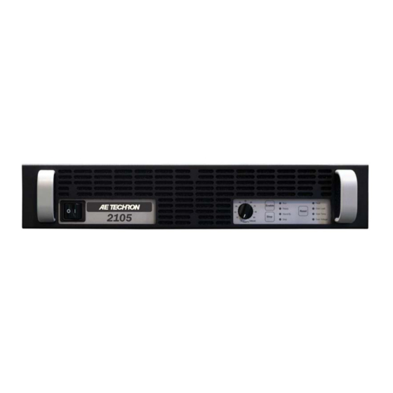
2105 OPERATOR’S MANUAL – SECTION 1 Figure 1.1 – 2105 Front Panel 1 Introduction The AE Techron 2105 is a high-power, DC-enabled Current mode response: DC-5 kHz (compen- • linear amplifier and integrated power supply that sation dependent); Voltage mode response: offers a wide bandwidth and exceptional control of DC-20 kHz at rated power. drift and distortion. The 2105 functions as a volt- Efficient design allows amplifier to occupy only • age or current source and operates using single- 2U height, and weigh only 46 lbs. phase power, making it ideal for use in the lab or Robust, linear power supply results in extreme- • classroom. Its linear design provides a very-low ly low noise; bi-level switch design limits heat noise floor and fast current rise times. Because dissipation to output devices. the 2105 has no ripple noise, no synching with the Provides precision control of output offset, DC • console is required. drift and gain linearity. Protection circuitry guards against input over- • The AE Techron brand is known throughout the loads, improper output connection (including world for its robust, low-noise gradient amplifiers shorted and improper loads), over-temperature, as well as its product service and support. -
Page 7: Amplifier Unpacking And Installation
2105 OPERATOR’S MANUAL – SECTION 2 2 Amplifier Unpacking and Along with any additional accessories purchased by the customer, all 2105 amplifiers ship with the Installation following: The 2105 amplifier is a precision instrument that • 2105 Amplifier can be dangerous if not handled properly. Lethal Accessories Kit (contains three 2.7-ohm resis- • voltages are present in both the AC input supply tors and four rubber feet) and the output of this amplifier. For this reason, • Power Cord safety should be your primary concern when you 2105 Operator’s Manual (USB drive) and Quick • setup and operate this amplifier. Start sheet Safety First Installation Throughout this manual special emphasis is The 2105 amplifiers are packaged in a rugged placed on good safety practices. The following powder-coated steel chassis. This chassis is 2U graphics are used to highlight certain topics that (rack units) tall, and has rack “ears” on each side require extra precaution. of the front panel for mounting to a standard EIA (Electronic Industries Association) rack. Remove ... -
Page 8: Connections And Startup
2105 OPERATOR’S MANUAL – SECTION 3 3 Connections and Startup This section details the wiring and startup pro- cedures for a single 2105 amplifier operating in Controlled-Voltage mode (factory default). Before connecting the amplifier, make sure the AC power cord is unplugged. WARNING Figure 3.1 – Close-up of the Output Terminal Resistor ELECTRIC SHOCK HAZARD. Output potentials can be lethal. Make 3.2.2 Connecting the Outputs connections only with AC Power OFF Connection to the output of the amplifier is to a and input signals removed. 3-position terminal strip with #8 screws. Wires Considerations for Controlled- terminated with #8 to ¼ in. ring terminals, tinned ... -
Page 9: Connecting The Ac Supply
2105 OPERATOR’S MANUAL – SECTION 3 connector is floating, allowing the connector to be used for Balanced input wiring. IMPORTANT: The Input Select switch can also function as a Ground Lift switch for the BNC Input connector. If circulating currents/ground loops/60-Hz Hum occur when using the BNC Figure 3.3 – Close-up of SIM card Input, move the Input Select switch to the right to lift the ground on the connector. -
Page 10: Start-Up Procedure
2105 OPERATOR’S MANUAL – SECTION 3 3. Depress the POWER switch to turn the amplifier ON. 4. Wait for the yellow READY and green RUN LEDs to illuminate. 5. Adjust the level of your input signal source to achieve the desired output level. 6. Turn up the Gain control on the amplifier Figure 3.6 – Sample of Configurations Setting Label until the desired voltage or power level is Review the factory-set supply voltage and ampli- achieved. fier configuration detailed on the label placed on 7. Adjust the input signal level to achieve the the side of the amplifier (see Figure 3.6). This desired output level. configuration can be changed by the user. See 3.5.1 Current-Mode Operation the “Advanced Configuration” section for more Before configuring your amplifier for Current mode ... -
Page 11: Amplifier Operation
2105 OPERATOR’S MANUAL – SECTION 4 4 Amplifier Operation Front-Panel Controls This section provides an overview of Front-Panel controls and indicators found on the 2105. 4.1.1 Power Switch The Power Switch controls the AC mains power to Figure 4.1 – Power Switch the amplifier. Switch to the ON position (|) to turn the amplifier on. Switch to the OFF position (O) to turn the amplifier off. See Figure 4.1. The Power Switch also serves as a Breaker. When the Breaker is tripped, the Power Switch moves to a neutral position between ON and OFF. To reset the Breaker, turn the amplifier OFF (O) and then turn it back ON (I). Figure 4.2 – Gain Control 4.1.2 Gain Control The Gain Control Knob increases/decreases the ... -
Page 12: Figure 4.4 - Main And Fault Status Indicators
2105 OPERATOR’S MANUAL – SECTION 4 Standby/Stop mode: The amplifier has been placed in Standby due to a Stop order: The Stop button on the amplifier front panel has been pushed or the amplifier has been configured to enter Stop mode on startup. See the “Advanced Configuration” section for information about con- figuring the amplifier for Startup in Stop mode. Figure 4.4 – Main and Fault Status Indicators Enable, Stop and Reset Buttons pressing the Reset button will return the amplifier The following details the results when each of the to Run mode if the condition causing the fault con- three Push Buttons are pressed on the amplifier dition has been cleared and the amplifier has been front panel. configured for startup in Run mode. If the ampli- fier has been configured for startup in Stop mode, Enable – When the amplifier is in Standby/Stop pressing the Reset button will place the amplifier mode, pressing the Enable button will release the in Standby/Stop mode. Press the Enable button to amplifier from Standby and place the amplifier in ... -
Page 13: Figure 4.6 - Fault Status Indicators
2105 OPERATOR’S MANUAL – SECTION 4 4.1.5 Fault Status Indicators ration of the unit, the amplifier may be placed in Four Fault Status indicators are located on the Standby mode when a fault condition occurs. Re- amplifier front panel (see Figure 4.4). These LEDs monitor the internal conditions of the amplifier fer to the chart in Figure 4.6 to determine the fault condition being indicated and the action required and will illuminate when a fault condition occurs. Depending on the fault condition and the configu- to clear the fault condition. -
Page 14: Back-Panel Controls And Connectors
2105 OPERATOR’S MANUAL – SECTION 4 Back-Panel Controls terminal block connector are tied to the amplifier and Connectors ground through a 4.7-ohm resistor, allowing the connectors to be used for Unbalanced input wir- This section provides an overview of Back-Panel ing. When the Input Select switch is in the RIGHT controls and connectors found on the 2105 ampli- position, the inverting (–) pin on the terminal block fier. Please refer to Figure 4.7 for visual locations. connector is floating, allowing the connector to be AC Supply - Standard 20 amp 3-pin IEC-type used for Balanced input wiring. The Input Select male connector. switch also functions as a Ground Lift switch for the BNC input connector. -
Page 15: Advanced Configuration
2105 OPERATOR’S MANUAL – SECTION 5 5 Advanced Configuration Removing Amplifier Top Cover The 2105 amplifier was designed to offer excep- Most internal configuration settings can be made tional versatility in operation. You can choose from by removing the amplifier’s top cover. a range of field-configurable options, including: IMPORTANT: Before removing the top cover, Operate with variable gain control or at a fixed • make sure the amplifier is turned off for at gain setting of 20. least 3-5 minutes and the AC mains are discon- Select Controlled-Current or Controlled-Voltage ... -
Page 16: Figure 5.1 - Gain Trim Control
2105 OPERATOR’S MANUAL – SECTION 5 5.2.1 Fixed Gain/Variable Gain Setting The 2105 amplifier ships with an enabled Gain Control knob (located on the amplifier front panel). To disable the Variable Gain control and set for a Fixed Gain of 20, locate and unplug the red con- nector from jumper J10. Then place a jumper on the left two pins at that location. See Figure 5.1. Figure 5.1 – Gain Trim Control 5.2.2 Controlled Voltage or Controlled Current Setting To allow the 2105 amplifier’s output voltage to be ... -
Page 17: Figure 5.4 - Run Mode/Stop Mode On Power-Up Setting
2105 OPERATOR’S MANUAL – SECTION 5 CAUTION In Controlled-Current Mode, the load is part of the amplifier circuit, and the relationship of the load to the amplifier is critical. For proper and safe operation in Controlled-Current mode, you must obverve the following guidelines: 1. Properly attach a load before operating the amplifier. Use only the Output and Sampled Common terminals. DO NOT use the Common terminal. 2. DO NOT use a blocking capacitor. The load must have a DC path. 3. Never leave the load open. If you feel the load must be fused, which could lead to a poten- tial open circuit, please contact AE Techron Application Engineering department. 4. Check to make sure the load has some inductive component. -
Page 18: Configuration Settings Located On The Power Supply Board
2105 OPERATOR’S MANUAL – SECTION 5 Configuration Settings Located on the Power Supply Board The following custom settings can be made via plug-in connectors located on the Power Supply Board: Amplifier Voltage Potential setting (high current • or high voltage) Bi-Level Power Supply setting • 5.3.1 Accessing the Power Supply Board Figure 5.6 – Accessing the Power Supply Board To access the Power Supply Board, follow the instructions given at the beginning of this Section to remove the top cover. The Power Supply Board is located to the right of the Main Board, as shown in Figure 5.6. 5.3.2 Changing Amplifier Voltage Potential The 2105 can be configured for High Current (90V) or High Voltage (180V) operation via user- selectable plugs on the Power Supply Board. Figure 5.7 – Location of Amplifier High-Voltage ... -
Page 19: Figure 5.10 - Bi-Level Power Switch Location
2105 OPERATOR’S MANUAL – SECTION 5 SIM card from the amplifier until it is complete- ly clear from the card bay. 4. Locate Bi-Level Power Switch, S1, a black, three-position switch at the rear of the card bay.(See Figure 5.10) 5. Move the Black switch to desired setting. If necessary, use a pointed, non-metallic object (such as a pen) to help in moving the switch. a. Automatic – Left Figure 5.10 – Bi-Level Power Switch Location b. Low – Middle c. High – Right Use the following general guidelines to select the best combination of settings to fit your requirements: 5.3.4 Selecting the Best Voltage Potential and Bi-Level Power... -
Page 20: Applications
2105 OPERATOR’S MANUAL – SECTION 6 6 Applications Conversely, when configured as a Controlled- Controlled Current Operation Current source (transconductance amplifier), the amplifier will provide an output current that is con- The procedures outlined in this section assume stant and proportional to the control (input) volt- competence on the part of the reader in terms of amplifier systems, electronic components, and age. If the load’s impedance changes, the amplifier good electronic safety and working practices. will seek to maintain this transconductance (ratio ... -
Page 21: Figure 6.3 - Factory-Installed Default Rc Network
2105 OPERATOR’S MANUAL – SECTION 6 When operating in Controlled Current (CC) mode, a compensation circuit is required to ensure ac- curate output current. Since the load is a critical circuit component in CC mode, the inductive and resistive values of the load will determine the required compensation values. While the factory- default compensation setting will be sufficient for some applications, the compensation setting may also be adjusted in the field. The following section describes methods for determining and setting proper compensation when operating in Figure 6.3 – Factory-installed Default RC Network Controlled-Current mode. STEP 2: Determine Required 6.1.3... - Page 22 2105 OPERATOR’S MANUAL – SECTION 6 components (a resistor (R) and a capacitor (C)) compensation, you determine that the default com- pensation will be insufficient for your load, then to be installed on the main board. To calculate the you will need to enable and install a custom RC approximate values required for each component, network. See STEP 6 below. use the following formulas. STEP 4: Enabling Your Compensation COMPENSATION FORMULAS: Setting. To find the value for the resistor (Rc) in the RC network: AE Techron 2100 Series amplifiers can be enabled ...
-
Page 23: Figure 6.4 - Custom Compensation Location
2105 OPERATOR’S MANUAL – SECTION 6 Figure 6.4 – Custom Compensation Location Observe the output current through a current monitor or current probe. Look for clean transition edges. The presence of ringing or rounding on the transition edges indicates compensation problems. (See Figure 6.5.) Figure 6.6 – Square Wave Showing a Decrease in R is Required Figure 6.5 – Compensation Effects on Waveform If a change in compensation is necessary, an ad- justment to the resistor component of the Compen- sation circuit is probably required. Figure 6.7 – Square Wave Showing an Increase in R is Required If the output current waveform is ringing, the circuit is underdamped: You have too much gain and should lower the resistance (see Figure 6.6). If the output current waveform is rounded, the circuit is overdamped: You have too little gain and should increase resistance (see Figure 6.7). If the output current waveform is neither under- damped or overdamped, but the top of the square-... -
Page 24: Remote Status And Control Using The Sim Interlock I/O Connector
2105 OPERATOR’S MANUAL – SECTION 6 When making adjustments: NOTE: Resistor: Increase or decrease resistance values If possible, use 1% metal film resistors. AE • in increments of +/- 10%. Techron discourages installation of potentiome- ters in the resistor location of the compensation Capacitor: Incrementally increase capacitor val- circuit because this can decrease stability and ues by a factor of 2 or 3. may increase inductance. After final adjustments have been made to the The parallel capacitor in the RC network serves • circuit, the final waveform for your planned appli- to increase stability but can be removed, if it is cation should be tested to confirm the amplifier’s not required for system stability. If the parallel compensation setting. capacitor is used, it will usually decrease the value of resistance needed. -
Page 25: Figure 6.10 - Remote Status And Reset Schematic
2105 OPERATOR’S MANUAL – SECTION 6 6.2.1 Remote Amplifier Status and Reset The SIM Interlock I/O Connector can be used to Note: When amp is normal, this pin is pulled to –24V through a 47.5K-ohm resistor; when amp create a circuit to monitor remotely one or more is in Overtemp state, transistor Q37 turns on and amplifier conditions, including Run status, Over- sources chassis ground as an output. Do not ex- temperature, Overload and Overvoltage. The cir- ceed 20 milliamps. cuit can also be constructed to allow remote reset An Overtemp condition will force the amp to of the amplifier when it is forced to Standby due to ... -
Page 26: Figure 6.11 - Remote Run/Standby Monitor
2105 OPERATOR’S MANUAL – SECTION 6 Note: When amp is normal, this pin is pulled to Note: When amp is normal, this pin is pulled to –24V through a 47.5K-ohm resistor; when amp –24V through a 47.5K-ohm resistor; when amp is in Overload state, transistor Q36 turns on and is in Overvoltage state, transistor Q29 turns on sources chassis ground as an output. Do not ex- and sources chassis ground as an output. Do not ceed 20 milliamps. exceed 20 milliamps. An Overload condition will not place the amplifier Reset from Standby in Standby when operating with the factory de- fault settings. In order to clear the fault condition, Purpose: Switch, when thrown, returns amp to reduce the input levels until the Fault LED turns ... -
Page 27: Figure 6.12 - Remote Enable/Standby
Remote Monitoring of Current Using the SIM-BNC Interlock connector located on the back panel of the amplifier, you can remotely monitor both voltage and current output. Use a male, 25-pin D-Sub connector and high- quality wire to build the desired circuits. Remote Monitoring of Current Output Purpose: Use a voltage meter to monitor output current. Method: Connect a voltage meter to monitor the output current being produced by the ampli- fier. Connect across PIN 6 (I MON+) and PIN 10 (Sampled Common). See Figure 6.13. Signal Type: DC Level when Asserted: 2105: 5A/V; 2110/2120: 20A/V Figure 6.13 – Remote Current Monitoring Level when Deasserted: 0V Information subject to change 97-2105006_7-16-2021... -
Page 28: Figure 6.14 - Remote Current Monitoring, Alternate Method
2105 OPERATOR’S MANUAL – SECTION 6 Remote Monitoring of Current Output - Alternate Method Purpose: Use a voltage meter to monitor output current when output is not balanced. Method: Connect a voltage meter to monitor the output current being produced by the ampli- fier. Connect across PIN 6 (IMON+) and PIN 19 (IMON-). See Figure 6.14. Signal Type: AC Level when Asserted: 2105: 2.5A/V; 2110/2120: 10A/V Level when Deasserted: 0V CAUTION: To avoid ground loops, isolation from ground must be provided. Use of a differential probe is recommended. Figure 6.14 – Remote Current Monitoring, Alternate Method Blanking Circuit Activation Purpose: Activate the blanking circuit that shuts ... -
Page 29: Amplifier Signal Flow
2105 OPERATOR’S MANUAL – SECTION 7 7 Amplifier Signal Flow AC Mains Power Power to the amplifier is connected through a 20- Input Signals amp IEC-type inlet connector with an integral EMI The input signal is routed from the SIM (Specialized filter network on the back panel. AC mains power is Input Module) on the back panel to the Main board. first routed through the front panel switch/breaker, From there, the signal is amplified through low-noise then to the Power Supply board. From there, the AC operational amplifier gain stages, compensation mains are distributed to the main power transform- networks, and current limiting/ODEP and then final ers, and then from the transformers back through the gain stage to the Output board. At the Output board, Power Supply board to the Main board. the signal is sent through pre-drivers, output stage drivers, then to the Output stage whose topology is The Power Supply board allows for easy configura- a full-complimentary, full-bridge, AB+B mode transis- tion of primary and secondary voltages. The Power tor design. Amplifier control and status is handled by Supply board also performs the “bi-level” function. logic circuits tied to the Display/Control board on the This allows the power supply rails to the Output sec- front panel. Protection is provided by current limiting tion to increase or decrease depending on demand circuits and special junction temperature simulation and keeps the voltage dropped across the outputs to ... -
Page 30: Maintenance
2105 OPERATOR’S MANUAL – SECTION 8 Clean Amplifier Filter and Grills 8 Maintenance 8.1.1 Tools Required Simple maintenance can be performed by the user The recommended equipment and supplies to help keep the equipment operational. The fol- needed to perform the functions required for this lowing routine maintenance is designed to prevent task are described below. problems before they occur. See the “Trouble- shooting” section, for recommendations for • Vacuum cleaner restoring the equipment to operation after an error Damp cloth (use water only or a mild soap • condition has occurred. diluted in water) To ensure adequate cooling and maximum ef- Preventative maintenance is recommended after ficiency of the internal cooling fans, the amplifier’s ... -
Page 31: Troubleshooting
2105 OPERATOR’S MANUAL – SECTION 9 9 Troubleshooting Visual Inspection Before attempting to troubleshoot the amplifier Introduction & Precautions while it is operating, please take time to complete This section provides a set of procedures for a visual inspection of the internal components of identifying and correcting problems with the 2105 the amplifier. amplifier. Rather than providing an exhaustive and 1. To perform a Visual Inspection, first turn the detailed list of troubleshooting specifications, this Breaker/Switch to the Off (O) position. section aims to provide a set of shortcuts intended 2. Disconnect the AC mains plug from the ampli- to get an inoperative amplifier back in service as fier. quickly as possible. -
Page 32: No Signal
1. Turn Off (O) the amplifier and disconnect the illuminated and the Interlock I/O Cable is being AC mains. used, the amplifier is being held in Remote 2. Remove Access Panel (see “Advanced Con- Standby by another device (see Figure 9.3). figuration”). For more information on 2105 Remote Opera- 3. Locate Fuse F1 (see Figure 9.2). Remove fuse tion, see the “Applications” section in this and inspect. Replace, if necessary, with same manual. type fuse (T1.6A L 250V). 3. If the connection to the Interlock – I/O Connec- tor or other input/output connection isn’t fully ... -
Page 33: Amplifier Overheats (Over Temp Fault Condition)
2105 OPERATOR’S MANUAL – SECTION 9 secure. Check all wiring and connections. curred, make sure fans are running, then remove the input signal from the amplifier. Allow the fans Amplifier Overheats (Over Temp to run for at least five minutes. When the amplifier Fault Condition) is sufficiently cool, it will automatically return to There are two possible reasons why the 2105 am- Run status. If the amplifier does not automatically plifier is overheating: return to Run, push the Reset button to reset the amplifier. 1. Excessive Power Requirements 2. Inadequate Airflow Fault LED is Illuminated 9.7.1 Excessive Power Requirements The 2105 contains protection circuitry that disables An amplifier will overheat if the required power ex- the amplifier if an output stage is behaving abnor- ceeds the amplifier’s capabilities. High duty cycles mally. This usually indicates an output transistor and low-impedance loads are especially prone to has shorted. - Page 34 2105 OPERATOR’S MANUAL – SECTION 9 Return Authorizations can be requested on our Please send all service units to the following ad- website or by contacting our Customer Service dress and be sure to include your Return Authori- Department. zation Number on the box. AE Techron, Inc. Please take extra care when packaging your am- Attn: Service Department / RMA# plifier for repair. It should be returned in its original 2507 Warren Street packaging or a suitable alternative. Replacement Elkhart, IN 46516 packaging materials can be purchased for a nomi- nal fee. Information subject to change 97-2105006_7-16-2021...
- Page 35 Not recommended for normal customer use. amplifier use; not recommended for normal customer use. Line has series resistor and unloaded will go from 0V (not ready) to -15V (ready), with an OPTOC BNC card the signal will go from 0V (not ready) to -1.2Vdc (ready) I MON + Differential Current Output current produced per voltage Current Monitoring: Connect a voltage meter to mon- AC or 2105: 5A/V Monitor + itor the output current being produced by the amplifier. 2110/2120: detect. 20A/V For unbalanced, for each 1V detected, current output is 5A (2105) or 20A (2110/2120). None No connection Not currently used. Blanking Blanking control Used in amplifiers with blanking Blanking Control: Use an external isolated 5V power ...
- Page 36 Ground ground - Interlock Standby or Stop after Error. Used with PIN 4 (Interlock) for simultaneous remote to Standby of all amps in a Common multi-amplifier system. OEM App Input Monitor Used to monitor the input signal OEM modification only; normally no connection. (OEM only) from an OEM DAC card; this is the actual input signal. I MON – Differential Current 2105: 5A/V Inverted I MON+ (PIN 6). Output Current Monitoring: Connect a voltage meter to mon- AC or (alt.: OEM Monitor – ; current produced per voltage detect. itor the output current being produced by the amplifier. 2110/2120: App) (- Input Monitor, 20A/V For each 1V detected, current output is 5A (2105) or 20A OEM only) (2110/2120). I SUM1–...
- Page 37 Pin # Function Description Signal Level when Level when Notes Applications Type Asserted Deasserted OverLoad –24V Remote Signal of Overload Condition: LED, when lit, Overload output When amp is normal, this pin is (amplifier output is pulled to –24V through a 47.5K-ohm signals Overload condition. Use a 6mA series resistor clipping). resistor; when amp is in Overload of 4.7K-ohm for LED or OPTO, tie to –24V source (PIN state, this pin is grounded. Do not 13). exceed 6 milliamps. OverVoltage ...
Need help?
Do you have a question about the 2105 and is the answer not in the manual?
Questions and answers