
Related Manuals for Aetechron 8700 Series


Summary of Contents for Aetechron 8700 Series
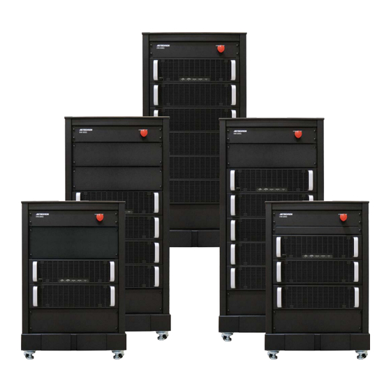
- Page 1 8700 Series Operator’s Manual Ultra-Wide-Bandwidth, High-Power Switch-Mode Amplifiers Models 8708, 8712, 8716, 8720, and 8724 574.295.9495 | www.aetechron.com 2507 Warren Street, Elkhart, IN 46516...
- Page 2 For Compliance Questions Only: Larry Shank 2507 Warren Street +1 574-295-9495 Elkhart, IN 46516 lshank@aetechron.com This Declaration of Conformity is issued under the sole responsibility of AE Techron, Inc., and belongs to the following product: Equipment Type: Industrial Power Amplifiers...
- Page 3 2507 Warren St. Elkhart, IN, 46516, U.S.A. receive an authorization to return the product for (574) 295-9495 service. All components must be shipped in a factory www.aetechron.com pack or equivalent which, if needed, may be obtained...
-
Page 4: Table Of Contents
Contents 1 Introduction ............................5 1.1 Configuration Options......................5 2 Amplifier Unpacking and Installation ....................6 2.1 Safety First ..........................6 2.2 Unpacking ..........................6 2.3 Check Contents ........................7 2.4 8700 Series Placement ......................7 3 Connections and Startup .......................8 3.1 Testing Before Controlled-Current Operation ...............8 3.2 Connecting the Load ......................8 3.3 Other DIP Switch Settings .....................9 3.4 Monitor and Sense Ports .......................9 3.5 Connecting the AC Supply ....................10 3.6 Start-up Procedure ......................4 ... -
Page 5: Introduction
8700 SERIES OPERATOR’S MANUAL – SECTION 1 Figure 1.1 – 8700 Series Front Panel 1 Introduction 1.1 Configuration Options Congratulations on your purchase of an 8700 series power amplifier. 8700 series A key to everyday product usability is quick and amplifiers are 400Vp, low-noise, DC-to- easy product (re)configuration. The 8700 series amplifier provides all key configuration controls on 250-kHz switch-mode amplifiers. The 8700 the back panel of the unit. Configuration options series provides a unique combination of available include: switch-mode and linear amplifiers. Switch- mode efficiency is combined with a low • Gain: Fixed or variable gain (0 to 40) • Current Limit: From 5% to rated limit (to noise floor and THD, while also benefitting protect fragile DUTs or where specified in the from high slew rates and wide bandwidth. Standard) The 8700 series is also able to safely drive DC Control: DC enabled or DC blocked and • both reactive and resistive loads of vary- DC Servo (for driving transformer-coupled ing impedances with no loss in rated output loads, coils) power. Input: Balanced and/or unbalanced •... -
Page 6: Amplifier Unpacking And Installation
8700 SERIES OPERATOR’S MANUAL – SECTION 2 2 Amplifier Unpacking and WARNING Installation 8700 series amplifiers are precision instruments Use caution when using a forklift to move this cabinet. Crushing bodily injury can that can be dangerous if not handled properly. Le- result if care is not taken during uncrating thal voltages are present in both the AC input sup- and installation. ply and the output of the amplifier. For this reason, safety should be your primary concern when you To uncrate the product, remove the crate’s setup and operate this amplifier. -
Page 7: Check Contents
1. Quick Start Guide 2. 8700 series Operation Manual on USB drive CAUTION DO NOT use the cabinet wheels to transport the cabinet over long dis- tances. The cabinet wheels should be used only for moving the cabinet over a short distance to position the cabinet in its permanent location. 2.4 8700 Series Placement 8700 series amplifiers are mounted on wheels to allow rolling on a flat, smooth surface.The cabinet wheels should be used only for moving the cabi- net over a short distance to position the cabinet in its permanent location. DO NOT use the cabinet wheels to move the cabinet over long distances. Figure 2.2 – Clearance Recommendations for Amplifier Placement To avoid possible tipping, always push the ampli-... -
Page 8: Connections And Startup
8700 SERIES OPERATOR’S MANUAL – SECTION 3 Figure 3.1 – 8700 series I/O Panel (back panel) 3 Connections and Startup This section details the wiring and startup pro- WARNING cedures for an 8700 series amplifier operating in Controlled-Voltage mode (factory default). Before ELECTRIC SHOCK HAZARD. connecting the amplifier inputs and outputs, make Output potentials can be lethal. Make sure the AC power is disconnected. connections only with AC Power OFF and input signals removed. 3.1 Testing Before Controlled-Current 3.2 Connecting the Load Operation 3.2.1 Preparation and Cautions IMPORTANT: If your application requires Con- trolled Current operation, the 8700 series amplifier ... -
Page 9: Other Dip Switch Settings
8700 SERIES OPERATOR’S MANUAL – SECTION 3 load across the terminals marked “OUTPUT” (posi- shielded to minimize noise and to guard against tive) and “GND” (ground). The GND terminal also possible feedback. can be connected to an external ground point such DIP switch #1, located on the back panel of the as the amplifier chassis, if desired. See Figure Master amplifier module (uppermost module in the 3.2. amplifier) can be used to enable/disable the unbal- anced input connector, and DIP switch #2 can be used to enable/disable the balanced input connec- tor. When these two DIP switches are placed in the UP position (factory default), the input connectors are enabled. When the DIP switches are placed in the DOWN position, the input connectors are disabled. Figure 3.2 – Connecting the Load See Figure 3.5 for DIP switch locations. Be sure to install the output safety cover after wir- ing the output connections. See Figure 3.3. Figure 3.3 – Output Safety Cover Connecting the Input Signal Figure 3.5 – DIP Switch Locations for Input Connector Enable/Disable Both an unbalanced Input BNC jack and a bal- anced Input “WECO” terminal block connector 3.3 Other DIP Switch Settings (mating WECO connector provided) are available Other DIP switches located on the amplifier mod- on the amplifier back I/O panel for signal input. ... -
Page 10: Connecting The Ac Supply
8700 SERIES OPERATOR’S MANUAL – SECTION 3 See the Applications section of this manual for DANGER information on using these ports The risk of lethal ELECTRICAL SHOCK exists when connecting AC mains! WARNING Disconnect the source before connect- ing AC power wires to the amplifier’s AC inputs. ELECTRIC SHOCK HAZARD. Power supply wiring should only be performed maximum rating no more than the rated current for ... - Page 11 8700 SERIES OPERATOR’S MANUAL – SECTION 3 Figure 3.7 – Three-Phase AC Mains Wiring 3. Open the access door on the back of the am- phase, 50-60 Hz, 208 VAC (or optional 400 VAC) plifier and locate the fuse and AC inlet panel with no more than 10% variance above or below near the bottom of the amplifier. Locate the the line voltage. The amplifier will not operate power block, which is mounted behind the fuse properly outside these limits. and AC inlet panel (see Figure 3.5). Connect protective grounding terminal to AC mains 4. Route the 10 AWG, 5 conductor power input ground before turning on power to prevent electric cable into the amplifier through the cable strain shock hazard. relief (located on the fuse and AC inlet panel). 5. Connect to the AC mains barrier strip as shown Do not disconnect or disable the protective in Figure 3.7. See Appendix B for wiring dia- grounding connection. Doing so causes a poten- grams of the complete AC power systems. tial electrical shock hazard.
-
Page 12: Start-Up Procedure
8700 SERIES OPERATOR’S MANUAL – SECTION 3 IMPORTANT Operation of the amplifier at frequencies above 100 kHz without an output load is NOT RECOMMENDED. The low-pass filter in your amplifier was de- signed to function with a load attached to the amplifier output. If the amplifier is operated without a load at frequencies above 100 kHz, higher than expected gains may result. An output load of 2-8 ohms is recommended for operation above 100 kHz. 3.6 Start-up Procedure 1. Turn down the level of your signal source. 2. Make sure the Emergency Stop button on the front panel is in the ON position (not depressed). 3. Make sure the back panel access door is closed and the breaker switch (near the bottom of the amplifier rear) is in the ON position. 4. Press the front-panel POWER switch to turn the amplifier ON. ... -
Page 13: Amplifier Operation
8700 SERIES OPERATOR’S MANUAL – SECTION 4 4 Amplifier Operation 1. High/Low Line error 2. Overtemp condition 4.1 Front-Panel Controls and Indicators 3. Fault condition This section provides an overview of Front-Panel 4. The user presses the front-panel power switch controls and indicators found on the 8700 series to the Standby (left) position. amplifier. Refer fo Figure 4.1 for component loca- In Standby mode, the amplifier’s low-voltage trans- tions. former is energized but the high-voltage transform- 4.1.1 Standby-Run Switch ers are not. The Standby-Run switch controls the power to the To release the amplifier from Standby mode: amplifier’s high-voltage transformers. Switch to 1. High/Low Line error: Clear the over- or the Run position (right) to energize the ampli- fier. - Page 14 8700 SERIES OPERATOR’S MANUAL – SECTION 4 drops to less than 100°C, the amplifier will re- mains. Once the fault condition has been cleared, sume operation. Note that in cases where the the amplifier will return automatically to Run mode. amplifier’s transformers have overheated, up If the High/Low Line indicator does not turn off or to15 minutes of cooling time may be required if the amplifier does not return from Standby, the before the amplifier can resume operation. See amplifier may require servicing. See the Trouble- the Overtemp Indicator topic in this section shooting section for more information. for more information. 4.1.5 Overtemp Indicator 3. Fault condition: Standby-Run switch to The amplifier monitors the temperature inside the Standby and then back to Run to reset the high-voltage transformers and in the output stage amplifier. If the fault condition recurrs or does heat sinks. The amber Overtemp indicator will light not clear, the amplifier may require servicing. and the amplifier will be placed in Standby mode See the Troubleshooting section for more when the temperature sensors detect a condition information. that would damage the amplifier. If the Overtemp 4. Power switch pressed: When the amplifier is pulse is extremely short, as in the case of defec- operating (Run mode), setting the front-panel ...
-
Page 15: Back-Panel Controls & Connectors
8700 SERIES OPERATOR’S MANUAL – SECTION 4 VOLTAGE MONITOR CURRENT MONITOR UNBALANCED INPUT BALANCED REMOTE OUTPUTS INPUT SENSE Figure 4.2 – Back Panel Controls and Connectors Back-Panel Controls & Connectors Output Terminals – Connect output lines from the load to this pair of high-current output terminals This section provides an overview of Back-Panel using 3/8-inch ring terminals. controls and connectors found on the 8700 series amplifier. Please refer to Figure 4.2 for component Back-Panel Safety Features locations. This section provides an overview of Back-Panel Unbalanced BNC Input Connector – This input safety features found on the 8700 series amplifier. option provides a standard unbalanced input. Please refer to Figure 4.3 for component loca- tions. -
Page 16: Advanced Configuration
• for DIP switch settings and descriptions. Controlled Current operation designed for loads from 1 mH to 5 mH. To locate the Master amplifier module, disconnect Install a custom compensation network for the amplifier from the AC source, and then open • Controlled Current operation. 8700 Series Default DIP Switch Settings, Master Amplifier Module Red = Default DO NOT CHANGE DIP SWITCH SETTINGS DOWN 1 UNBALANCED INPUT 2 BALANCED INPUT 3 DC SERVO 4 OPERATION MODE... - Page 17 8700 SERIES OPERATOR’S MANUAL – SECTION 5 unused input connector can help to minimize noise WARNING going into the amplifier. SW#2: Balanced Input ELECTRIC SHOCK HAZARD. When this switch is in the UP position, the bal- Follow these safety precautions before anced WECO input connector is enabled and opening the amplifier’s back access door: can be used to send an input signal to the ampli- • Disconnect the AC power supply. fier. When this switch is in the DOWN position • Wait at least 3-5 minutes after (default), this connector is disabled. Note that disconnecting AC power before opening the access door.
- Page 18 SW#7: Control Configuration pensation 2 network. For information on installing Do not change the Control Con- IMPORTANT: figuration switch on any 8700 series amplifier a custom compensation network, see Section 5.2 Master or Follower module unless instructed “Internal Configuration.” For more information by AE Techron Technical Support. Product on Controlled-Current operation, including instruc- failure could occur.
- Page 19 0.125Ω 0.00Ω SW#17: Electronic Gain Matching Do not change the Electronic Figure 5.3 – Synthetic Impedance Switch IMPORTANT: Gain Matching switch on any 8700 series Configurations amplifier Master or Follower module unless SW#21 - #24: Current Limit instructed by AE Techron Technical Support. These four switches control the current-limit set- Product failure could occur.
- Page 20 8700 SERIES OPERATOR’S MANUAL – SECTION 6 6 Applications 6.1 Controlled-Current Operation 6.1.1 Controlled-Voltage vs. Controlled- Current Modes of Operation AE Techron 8700 series amplifiers can be field- configured to operate as Voltage Amplifiers (Voltage-Controlled Voltage Source) or as Trans- conductance Amplifiers (Voltage-Controlled Figure 6.1 – Input to Output Comparison, Current Source). The mode selection is made via Controlled-Voltage Operation the back-panel DIP switch #4. See the Advanced Configuration section for more information. When configured as a Controlled-Voltage source (voltage amplifier), the amplifier will provide an output voltage that is constant and proportional to the control (input) voltage. If the load’s imped- ance changes, the amplifier will seek to maintain this ratio of input to output voltage by increasing or decreasing the current it produces, as long as it is within the amplifier’s ability to create the required Figure 6.2 – Input to Output Comparison, Controlled-Current Operation current. Use this mode if you want the output volt- age waveform to be like the input waveform (see Figure 6.1). When asked to operate in this way, any current ...
- Page 21 8700 SERIES OPERATOR’S MANUAL – SECTION 6 with DIP switch settings will be sufficient for many taching a load before configuring your amplifier for applications, this compensation setting may also Controlled Current operation. This will allow you be adjusted in the field by installing a custom com- to verify that the input signal and the amplifier are pensation network. The following section describes operating correctly. methods for determining proper compensation Once this initial check is completed, power down requirements when operating in Controlled-Current the amplifier, attach your load, and move the mode. Operation Mode DIP switch (SW#4, located on the Master amplifier module’s back panel) to the 6.1.3 Controlling Compensation for CC Operation DOWN position to place the amplifier in CC mode. AE Techron 8700 series amplifiers can be config- STEP 2: Determine Required Compensation. ured for either Controlled Voltage (CV) or Con- When operating an amplifier in Controlled- trolled Current (CC) mode of operation. When Current mode, the load becomes an integral part operating the amplifier in Controlled Voltage (CV) of the system. In order to determine the required mode, compensation is not required. However, compensation for your load, consulting the follow- when operating in Controlled Current (CC) mode, ing table to determine the approximate compen- the amplifier load becomes an integral part of the sation capacitance (CC) required based on the ...
- Page 22 8700 SERIES OPERATOR’S MANUAL – SECTION 6 STEP 3: Enable Compensation Network low level (typically 0.25 to 2.0 volts). A limited-rise- time, repetitive pulse of low duty cycle is preferred. If your load inductance is between 75 μH and 1 mH, and your load resistance is less than 5 ohms, Observe the output current through a current then you can likely use Compensation Network monitor or current probe. Look for clean transition 1 for your application. If your load inductance is edges. The presence of ringing or rounding on the between 1 mH and 5 mH, and your load resis- transition edges indicates compensation problems. tance is less than 5 ohms, then you can likely use (See Figure 6.5.) Compensation Network 2 for your application. If a change in compensation is necessary, an ad- (See Figure 6.3). These compensation networks justment to the resistor component of the Compen- are enabled when Compensation Network 1 DIP sation circuit is probably required. switch (SW#6) or Compensatlon Network 2 DIP switch (SW#5) on the Master amplifier module is If the output current waveform is ringing, the circuit set to the ON (UP) position. is under damped: You have too much compensa- tion and should lower the resistance (see Figure If your load inductance falls outside of these ranges, or if your load resistance is greater than 5 6.6). ohms, please contact AE Techron Technical Sup- port for assistance. STEP 4: Verifying Operation Figure 6.6 – Square Wave Showing a ...
-
Page 23: Driving Reactive Loads
8700 SERIES OPERATOR’S MANUAL – SECTION 6 If the output current waveform is neither under ters in the resistor location of the compensation damped or over damped, but the top of the square circuit because this can decrease stability and wave is not level, then you should instead de- may increase inductance. crease the capacitor value (see Figure 6.8). The parallel capacitor in the RC network serves • to increase stability but can be removed, if it is not required for system stability. If the parallel capacitor is used, it will usually decrease the value of resistance needed. In multiple amplifier systems, expect to decrease • Figure 6.8 – Square Wave Showing a the value of R5 in series systems by 1/2. Decrease in C is Required 6.2 Driving Reactive Loads When making adjustments: Like all switching amplifiers, 8700 series ampli- Resistor: Increase or decrease resistance values fiers are able to reuse the energy returned from in increments of +/- 10%. reactive loads. Unlike purely resistive loads, loads Capacitor: Incrementally decrease capacitor val- with some reactance (either capacitive or induc- ues by a factor of 2 or 3. tive) will store energy during part of a cycle, and then release some of this energy back later. This After final adjustments have been made to the energy is transferred back to the load through the circuit, the final waveform for your planned appli- amplifier’s power supply. This allows the amplifier ... -
Page 24: Maintenance
8700 SERIES OPERATOR’S MANUAL – SECTION 7 7 Maintenance • Vacuum cleaner Damp cloth (use water only or a mild soap • Simple maintenance can be performed by the user diluted in water) to help keep the equipment operational. The fol- To ensure adequate cooling and maximum ef- lowing routine maintenance is designed to prevent ficiency of the internal cooling fans, the amplifier’s problems before they occur. See the Trouble- front and rear grills should be cleaned periodically. shooting section, for recommendations for re- To clean the amplifier grills and filter, complete the storing the equipment to operation after an error following steps: condition has occurred. 1. Turn the amplifier OFF. Disconnect the ampli- Preventative maintenance is recommended after fier from its power source. the first 250 hours of operation, and every three 2. The front grill for each amplifier module is months or 250 hours thereafter. If the equipment secured to the module front panel by magnets. environment is dirty or dusty, preventative mainte- Pull out on the grill to release each one from nance should be performed more frequently. the front panel. 3. Remove the filter located behind the front grill. WARNING 4. Using a vacuum cleaner, vacuum the front ventilation grill and the grill filter. ELECTRIC SHOCK HAZARD. -
Page 25: Troubleshooting
8700 SERIES OPERATOR’S MANUAL – SECTION 8 8 Troubleshooting 3. Wait three to five minutes for the Power Supply capacitors to discharge. 8.1 Introduction & Precautions 4. Open the back access door and check the fol- lowing: This section provides a set of procedures for Check to make sure the breaker switch on identifying and correcting problems with the 8700 • all amplifier modules is in the ON position. series amplifier. Rather than providing an exhaus- I nspect the modules for loose or discon- tive and detailed list of troubleshooting specifica- • nected wires or connectors. tions, this section aims to provide a set of short- Inspect the bus bars connecting the ampli- cuts intended to get an inoperative amplifier back • fier module’s outputs for any signs of char- in service as quickly as possible. ring or melting. The procedures outlined in this section are direct- Inspect the entire lengths of wires and • ed toward an experienced electronic technician; cables for breaks or other physical damage. it assumes that the technician has knowledge of 5. If there is any physical damage to the amplifier, typical electronic repair and test procedures. -
Page 26: Run/Standby Led Remains Amber
8700 SERIES OPERATOR’S MANUAL – SECTION 8 amplifier’s internal transformers may need to be 8.7.2 Check for Inadequate Airflow 1. Check air filters. Over time they can become replaced. Please see the Factory Service infor- dirty and worn out. It is a good idea to clean mation at the end of this section. the air filters periodically with a mild detergent 8.6 Run/Standby LED Remains Amber and water. 2. Visually inspect fans to assure correct op- When the Run/Standby LED is lit solid amber, the eration while amplifier is On (I). When an amplifier is in Standby mode. Press the Power OverTemp fault occurs, the amplifier fans will switch to the ON position to place the amplifier in automatically be placed in continuous high- Run mode. speed operation. Any inoperative, visibly slow, or reverse-spinning fan should be replaced. If the amplifier does not return to run mode, check Please see the Factory Service information at to see if the High/Low Line, Overtemp, or Fault the end of this section. LEDs are lit, and then follow the instructions in An OverTemp condition places the amplifier in this section for remedying the fault condition and Standby mode. If the OverTemp pulse is ex- returning the amplifier to Run mode. -
Page 27: Factory Service
8700 SERIES OPERATOR’S MANUAL – SECTION 8 To clear the Fault condition, follow these steps: 8.9 Factory Service If the troubleshooting procedures are unsuccess- 1. Turn off the signal source. ful, the amplifier may need to be returned for 2. Turn off the AC mains. Factory Service. All units under warranty will be 3. Turn AC mains power back on. If the Fault serviced free of charge (customer is responsible LED doesn’t illuminate again, press the Power for one-way shipping charges as well as any cus- switch to place the amplifier in Run mode and tom fees, duties, and/or taxes). Please review the turn the signal source on. Warranty at the beginning of this manual for more 4. If the Fault LED is still illuminated and the Fault information. condition doesn’t clear, return the amplifier for All service units must be given Return Authoriza- Factory Service. See the Factory Service infor- tion by AE Techron, Inc. before being returned. mation at the end of this section. Return Authorizations can be requested on our website or by contacting our Customer Service CAUTION Department. Please take extra care when packaging your am- Shut off the signal source before reset- ting the amplifier. -
Page 28: Appendix A: Gain Dip Switch Settings
8700 SERIES OPERATOR’S MANUAL – APPENDIX A Appendix A: Gain DIP Switch Settings Use this chart to determine the required settings switches ON = Gain of 39.85, all switches OFF = for DIP switches 9 through 16 to achieve the am- gain of 0 (signal will not be amplified). plifier gain you need for your application. Note: All ON = DIP Switch UP OFF = DIP Switch DOWN SW#9 SW#10 SW#11 SW#12 SW#13 SW#14 SW#15 SW#16 Gain 39.85 39.69 39.54 39.38 39.22 39.06 38.91 38.75 38.60 38.44 38.29 38.13 37.97 37.81 37.66 37.50 37.35 37.19 37.04 36.88 36.72... - Page 29 8700 SERIES OPERATOR’S MANUAL – APPENDIX A ON = DIP Switch UP OFF = DIP Switch DOWN SW#9 SW#10 SW#11 SW#12 SW#13 SW#14 SW#15 SW#16 Gain 33.29 33.13 32.97 32.81 32.66 32.50 32.35 32.19 32.04 31.88 31.72 31.56 31.41 31.25 31.10 30.94 30.79 30.63 30.47 30.31 30.16 30.00 29.85 29.69 29.54 29.38 29.22 29.06 28.91 28.75 28.60 28.44...
- Page 30 8700 SERIES OPERATOR’S MANUAL – APPENDIX A ON = DIP Switch UP OFF = DIP Switch DOWN SW#9 SW#10 SW#11 SW#12 SW#13 SW#14 SW#15 SW#16 Gain 25.63 25.47 25.31 25.16 25.00 24.85 24.69 24.54 24.38 24.22 24.06 23.91 23.75 23.60 23.44 23.29 23.13 22.97 22.81 22.66 22.50 22.35 22.19 22.04 21.88 21.72 21.56 21.41 21.25 21.10 20.94 20.79...
- Page 31 8700 SERIES OPERATOR’S MANUAL – APPENDIX A ON = DIP Switch UP OFF = DIP Switch DOWN SW#9 SW#10 SW#11 SW#12 SW#13 SW#14 SW#15 SW#16 Gain 17.97 17.81 17.66 17.50 17.35 17.19 17.04 16.88 16.72 16.56 16.41 16.25 16.10 15.94 15.79 15.63 15.47 15.31 15.16 15.00 14.85 14.69 14.54 14.38 14.22 14.06 13.91 13.75 13.60 13.44 13.29 13.13...
- Page 32 8700 SERIES OPERATOR’S MANUAL – APPENDIX A ON = DIP Switch UP OFF = DIP Switch DOWN SW#9 SW#10 SW#11 SW#12 SW#13 SW#14 SW#15 SW#16 Gain 10.31 10.16 10.00 9.85 9.69 9.54 9.38 9.22 9.06 8.91 8.75 8.60 8.44 8.29 8.13 7.97 7.81 7.66 7.50 7.35 7.19 7.04 6.88 6.72 6.56 6.41 6.25 6.10 5.94 5.79 5.63 5.47...
- Page 33 8700 SERIES OPERATOR’S MANUAL – APPENDIX A ON = DIP Switch UP OFF = DIP Switch DOWN SW#9 SW#10 SW#11 SW#12 SW#13 SW#14 SW#15 SW#16 Gain 2.66 2.50 2.35 2.19 2.04 1.88 1.72 1.56 1.41 1.25 1.10 0.94 0.79 0.63 0.47 0.31 0.16 Information subject to change 96-8007392_04-24-24...
-
Page 34: Appendix B: Amplifier Module Wiring Diagrams
8700 SERIES OPERATOR’S MANUAL – APPENDIX B Appendix B: Amplifier Module Wiring Diagrams Information subject to change 96-8007392_04-24-24... - Page 35 8700 SERIES OPERATOR’S MANUAL – APPENDIX B Information subject to change 96-8007392_04-24-24...
- Page 36 8700 SERIES OPERATOR’S MANUAL – APPENDIX B Information subject to change 96-8007392_04-24-24...
- Page 37 8700 SERIES OPERATOR’S MANUAL – APPENDIX B Information subject to change 96-8007392_04-24-24...
- Page 38 8700 SERIES OPERATOR’S MANUAL – APPENDIX B Information subject to change 96-8007392_04-24-24...
- Page 39 8700 SERIES OPERATOR’S MANUAL – APPENDIX B Information subject to change 96-8007392_04-24-24...
- Page 40 8700 SERIES OPERATOR’S MANUAL – APPENDIX B Information subject to change 96-8007392_04-24-24...
- Page 41 8700 SERIES OPERATOR’S MANUAL – APPENDIX B Information subject to change 96-8007392_04-24-24...
Need help?
Do you have a question about the 8700 Series and is the answer not in the manual?
Questions and answers