Table of Contents
Advertisement
Quick Links
C R A F T S M E N ,
I N C .
Assembly Instructions
Model 7237
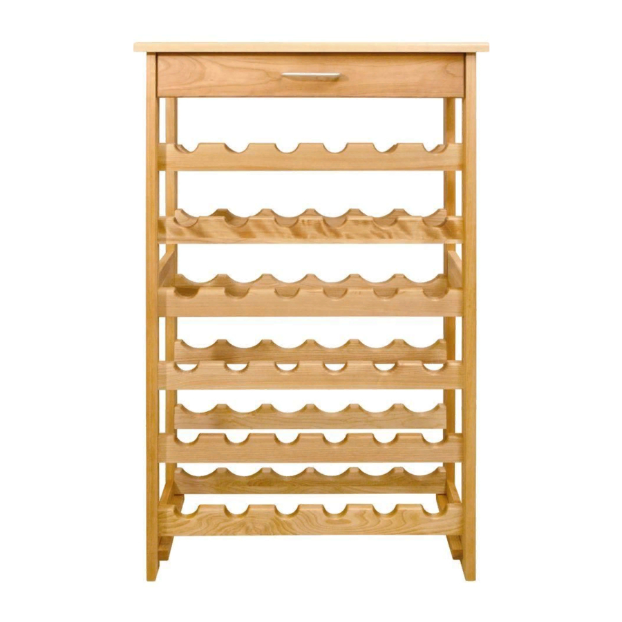
Wine Rack
GENERAL:
1. You have purchased model 7237. Overall dimensions of an assembled unit is 24" x 13" x 40".
2. Should you need assistance or need to replace a damaged or missing part, DO NOT
RETURN THE UNIT TO THE STORE where you purchased it, simply give us a call at
607-652-7321 from 7:30 - 4:00 PM Eastern time and we'll send you the prepaid part via UPS
usually that same day!
3. Read the assembly instructions and the enclosed brochure before beginning assembly.
Assembly is very easy if you read and follow the instructions step by step.
4. Tools required: Phillips screwdrivers, medium and small; medium flat blade screwdriver, pliers
and a hammer.
Advertisement
Table of Contents

Subscribe to Our Youtube Channel
Related Manuals for CATSKILL 7237


Summary of Contents for CATSKILL 7237
- Page 1 Wine Rack GENERAL: 1. You have purchased model 7237. Overall dimensions of an assembled unit is 24” x 13” x 40”. 2. Should you need assistance or need to replace a damaged or missing part, DO NOT RETURN THE UNIT TO THE STORE where you purchased it, simply give us a call at 607-652-7321 from 7:30 - 4:00 PM Eastern time and we’ll send you the prepaid part via UPS...
-
Page 2: Parts List
DF-7200 Rack Top 24” x 13” Drawer Back (1) TT-7200 BBK-7200 Bottom Side Cleat 9” x 3/4” x 3/4” (2) BSC-7237 Drawer Side Right (1) DS/R-7200 Top Side Brace 7 1/2” x 3 1/2” (2) Drawer Side Left (1) B-TS-7237 DS/L-7200 Middle/Bottom Side Brace 7 1/2”... -
Page 3: Hardware List
HARDWARE LIST Small 5/8” Wood Screw (4) Bastion Post (2) SKRU 5/8” #6F B-POST 1” Steel Pin (24) PIN 1” 3/4” Steel Pins (28) PIN 3/4” Small 3/8” Machine Screws (2) SKRU-M4-10 Bastion Barrel Nut (2) B-NUT Pan Head Machine Screws (2) SKRU 1”... - Page 4 STEP 1 SIDE ASSEMBLY PART I Look at illustration 1 closely, as all 4 legs are different. Note that the back legs have 3 holes near the top. Tap/insert 1” pins into the ends of the Side Braces. The Top Side Braces are wider than the 2 identical Middle/Bottom Braces.
- Page 5 STEP 2 SIDE ASSEMBLY PART II Attach Table Top Sticks to the top inside of each Side with 1 1/4” #8 screws. See illustration 2. Make sure the countersunk (reamed out) holes on the long narrow edge face downward & that the small pilot holes on the inside face of the stick face out.
- Page 6 STEP 3 GLIDE ASSEMBLY Attach Drawer Glides to Table Top Sticks. Look at the Glides, the narrow piece (with 2 sets of 3 holes and a punched out square stop at each end) attaches to the inside of the Table Top Sticks with the front end of the Glide flush with the front edge of the stick.
-
Page 7: Main Assembly
STEP 4 MAIN ASSEMBLY BRACE PREP: Insert/tap 3/4” pins into both ends of the Top Back Brace, Bottle Neck, and Bottle Bottom Support Braces until seated. See illustration 4A. Look at the Rack Sides/Illustrations to determine left & right Sides. Sides are mirror images of each other. The Bottle Neck Support Braces go toward the front, and their pilot holes on the inside of the Rack Legs start 8 5/8”... - Page 8 ILLUSTRATION 4B...
-
Page 9: Drawer Assembly
STEP 5 DRAWER ASSEMBLY Attach Drawer Back to the Drawer Sides with four 1 1/4” #8 Screws. There are left and right sides. Make sure the slots that run the length of the sides are aligned with the slot in the Drawer Back to accept the Drawer Bottom. - Page 10 STEP 6 ATTACH RACK TOP Attach the top to the rack base with four 2” #8 screws. This is accomplished by inserting the screws up through the table top sticks that were attached to the Rack sides in step 4. Some people will find it easier to attach the top with the unit upright.
-
Page 11: Attach Drawer
STEP 7 ATTACH DRAWER With unit upright, align the slots on the outside of the Drawer Sides with Drawer Glides attached to the Table Top Sticks. When both sides are aligned, push the drawer all the way in until it hits the Top Back Brace. - Page 12 CITY ______________________________________ STATE _________________________ ZIP _______ Catskill Craftsmen, Inc. Please make checks payable to: Catskill Craftsmen Inc. 15 West End Ave. 15 West End Ave. Stamford, NY 12167-1296 Stamford, NY 12167-1296 C R A F T S M E N ,...
Need help?
Do you have a question about the 7237 and is the answer not in the manual?
Questions and answers