Table of Contents

Subscribe to Our Youtube Channel
Related Manuals for Plum ZAB-14


Summary of Contents for Plum ZAB-14
- Page 1 Boiler regulator ZAB-14 FOR BIOMASS BOILERS WITH TWO FEEDERS ** room panel ecoSTER200- is not part of standard equipment SERVICE AND ASSEMBLY MANUAL EDITION: v1.2 APPLICABLE TO MODULE A PANEL SOFTWARE: v08.30.xx v08.13.xx 11-2015...
- Page 3 PRINCIPLES FOR USAGE OF Individual Fuzzy Logic CONTROLLED BOILER: The regulator must be programmed individually for the given type of boiler and fuel, pkt.23.1! It is inadmissible to change the type of gear-motor, fan, and to make other changes in the boiler fittings which can influence the burning process.
-
Page 5: Table Of Contents
TABLE OF CONTENTS SAFETY ..........7 12.4 Protective connection ....31 General information ......8 12.5 Control module disassembly ..31 Information about documentation ... 8 12.6 Exchanging parts and subassemblies31 Storage of documentation...... 8 12.7 Replacing mains fuse ....31 Applied symbols ........ - Page 6 15.23 Parameter A, B and C Individual Fuzzy 19.6 Integration time constant ..... 50 Logic ..........47 It is recommended to set this parameter within 16. Mobile grate SERVICE SETTINGS ..47 the range of 80 – 140 [by default: 110]. .. 50 17.
-
Page 7: Safety
means fuse, selected SAFETY appropriately to the applied loads, Requirements concerning safety Regulator cannot be used if its casing described in detail in individual chapters of or cables are damaged. Withdraw the this manual. Apart from them, the following device from exploitation immediately requirements should... -
Page 8: General Information
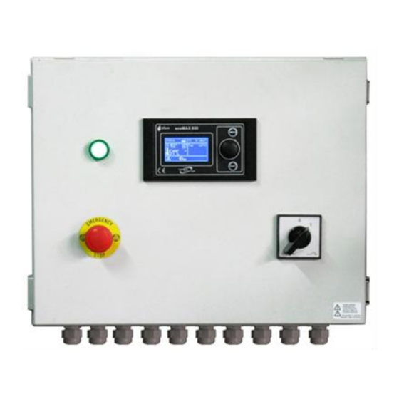
Outside (under the cover) there is a equipment control panel regulator modules, emergency button, signalling installation switch. ZAB-14 can be used within a household and in slightly industrialized buildings. Moreover, the regulator is intended to be enclosed on a boiler vicinity boiler Recycle product manufacturer. -
Page 9: Regulator Instruction Manual
REGULATOR INSTRUCTION MANUAL ZAB-14... -
Page 10: Structure - Main Menu
HUW settings HUW preset temp. 7. Structure – main menu HUW operations mode HUW tank hysteresis Main menu HUW disingection Information *Auto detect. SUMMER Boiler settings *Activ temp SUMMER HUW settings *Deactiv temp SUMMER *Mixer 2 settings ** Work according to schedule *HUW operations mode Night-time decrease General settings:... -
Page 11: Operating The Regulator
4. field of factors influencing preset boiler temperature: ,,T” - symbol of decreasing 8. Operating the regulator preset boiler temperature from opening This section briefly describes of room thermostat contacts; ,,S” - regulator should be operated. symbol decreasing preset boiler temperature according decrease... -
Page 12: Activating The Regulator
the regulator should be in the “stand-by” mode described herein. Fig. 3 Right window in mixer 1 view setup.. Fig. 6 Boiler activation screen. The right window on the main screen can It is possible to activate the boiler (press also present fuel level view, provided that encoder knob and select setting), or to set its the fuel level parameter is set properly. - Page 13 If it is active, press Touch and Play button blow parameter. In some instances, the and activate the regulator. regulator extends cleaning time before Feed the fuel manually by activating the firing-up in order to make sure that no feeder.
-
Page 14: Operation
operation cannot be continued automatically 8.7 OPERATION in the I.FuzzyLogic service crew must intervene. After mode removing causes of impossibility to fire-up, This mode can be activated in the menu: the boiler must be restarted. Regulation mode The Individual Fuzzy Logic function, the 8.6 OPERATION parameters of which are selected individually this... -
Page 15: Operation In The Standard Mode
SUPERVISION mode. Fig. 11 Output modulation hystereses H1 and H2. 8.8 Operation in the Standard mode The ZAB-14 boiler regulator is equipped with If the boiler temperature reaches the preset boiler output modulation mechanism, which value, regulator will... -
Page 16: Putting Out
into the SUPERVISION mode, and to supply as much heat, as the CH system requires at Parameters should be selected in the time. such way, that boiler In the SUPERVISION mode, the regulator temperature would gradually supervises the furnace, so that it would not decrease when this mode is active. -
Page 17: Standstill
8.11 STANDSTILL In the STANDSTILL mode, the boiler is put 8.13 Hot utility water settings HUW The device controls temperature of the hot out and awaits signal to resume heating. utility water - HUW – tank, provided that a A signal to start heating can be: HUW temperature sensor is connected. -
Page 18: Huw Tank Disinfection
ecoSTER200. Upon activation SUMMER function enabled thermostat, preset mixer circuit automatically, on the basis of readouts from temperature will be decreased, which, if the weather sensor. This functionality is proper decrease value is selected, will stop enabled with the following parameters: growth of temperature in the heated room. -
Page 19: Weather Controlled Operation
this setup, ecoSTER200 room Note: during trial and error selection of thermostat can: appropriate heating curve, it is necessary to exclude influence of the room thermostat on - decrease the heating cycle temperature by regulator operation (regardless of whether a constant value when the preset room the room thermostat is connected or not), by temperature is reached. -
Page 20: Description Of Settings For Night-Time Decreases
Buildings with poor thermal insulation require higher heating curves, whereas for buildings which have good thermal insulation, the heating curve can have lower value. The regulator can increase or decrease the preset temperature, calculated in accordance with the heating curve, if it exceeds the temperature range for the Fig. -
Page 21: Circulating Pump Control
Fig. 19 Fuel level service. mixing expansion module to the ZAB-14 Select and confirm “YES” to set the fuel level regulator. to 100%. The settings can be found in: Caution: The fuel can be replenished at any Night-time decrease >... -
Page 22: Cooperation With Secondary Feeder
time, it is possible to clean the boiler Fuel type selection automatically with the use of the parameter: regulator also equipped with Service settings > Boiler settings > function of selecting fuel type, i.e. its calorific Furnace cleaning value expressed in kW. Fuel type is suited to includes service parameters... -
Page 23: Work According To A Schedule
Fig. 20 View of manual control window, where OFF means that the device is off, and ON - that it is on. Note: prolonged activity of fan, feeder or other executive device can cause a hazard. 8.29 Work according to a schedule boiler deactivated time... - Page 25 REGULATOR INSTALLATION AND SERVICE SETTINGS MANUAL ZAB-14...
-
Page 26: Hydraulic Diagrams
, where: 1 – boiler with Fig. 22 feeder, 2 – ZAB-14 regulator, 3 – regulator control panel, 4 – boiler temperature sensor, 5 – return temperature sensor, 6 -temperature sensor—weather, 7 – room thermostat, 8 –mixer servo, 9 - temperature sensor –... -
Page 27: Scheme 2
Diagram with thermostatic three-way valve which protects the temperature of return Fig. 23 water , where:1 – boiler with feeder, 2 – ZAB-14 regulator, 3 – regulator control panel, 4 –boiler temperature sensor, 5 – return temperature sensor, 6 – central heating cycle pump, 7 – thermostatic three- way valve, 8 –throttle (poppet) valve, 9 –... -
Page 28: Scheme 3
, where:1 – boiler, 2 – ZAB-14 regulator, 3 – control panel, 4 – boiler temperature sensor, 5 – return temperature sensor, 6- central heating cycle pump, 7 – thermostatic three- way valve (protecting boiler return), 8 –... - Page 29 CONTINUED SUGGESTED SETTINGS: menu mixer settings 1,2,3,4 Mixer weather control 1, 2, 3, 4 Mixer heating curve 1 0.2 – 0.6 service settings -> mixer 1 settings Mixer support 2 on, floor service settings -> mixer 2 settings Max. pre-set mixer temp. 2 50 C service settings ->...
-
Page 30: Technical Data
~230V/400V; 50Hz; three phase supply Display Graphic 128x64 Regulator current Control panel: I = 0.08 A consumption 164x90x40 mm External dimensions ZAB-14: Execution module: Maximum rated current: 495x400x205 mm Upper feeder 2.5A(2.5)A Total weight of the 10,3kg Lower feeder 1.6(1.6)A... -
Page 31: Enclosure Conditions
In case of ordering spare parts or subassemblies, please provide supplier with necessary data read out from the ZAB-14 regulator rating plate. 12.7 Replacing mains fuse PG13.5 cable gland, 4 pcs. Dławica kablowa PG13,5, 4 szt. Dławica kablowa PG07, 14 szt. -
Page 32: Control Panel Replacement
regulator operate improperly if the control panel incompatible with executive module. Fig. 28 Fuse replacement, where: 1 – fuse, 2 – fuse socket. 12.9 Executive module replacement In order to remove the fuse, push in its The requirements are the same as those socket with a flat screwdriver and turn it for replacement of the control panel. -
Page 33: Current-Carrying Capacity Of The Regulator
Disconnect supply source prior to disassembly of ZAB- opening enclosure cover. 13.1 Current-carrying capacity of the regulator A maximum network current consumed 13.3 Description of strip terminals regulator along with terminals (controlled devices) peripherals cannot exceed 6A. It does 230/400V~ not include heater current which is Terminal PE/N/L... - Page 34 LV terminals (sensors) terminals (controlled Continued Terminal Function devices) 230/400V~ Boiler temp. sensor (OFF) Mixer 1 servo HL (ON) Feeder temp. sensor Mixer 1 pump Return temp. sensor HUW temp. sensor Alarm Weather sensor Exhaust temp. sensor Ash removal Room thermostat 1 Mixer temp.
- Page 35 MOUNTING PLATE ZAB-14 Fig. 29 Diagram for electric connections...
-
Page 36: Connecting Temperature Sensors
13.4 Connecting temperature 13.5 Connecting weather sensor sensors The regulator cooperates only with a weather sensor of the CT4-P type. The The regulator cooperates only with CT4i sensor should be installed on the coldest and CT2S sensors. It is forbidden to use wall of the building, usually this is the different sensors. -
Page 37: Circuits
The regulator cooperates only with an 13.7 Connecting room thermostat exhaust temperature sensor type CT2S. for mixer circuits In order to inspect the sensor, it is Room thermostats connected necessary very precise executive module B as per influences multimeter – otherwise, the sensor can mixer 1 and mixer 2 circuits. - Page 38 Fig. 31 Example of connection of a reserve boiler regulator in the OFF mode, if the pellet to ZAB-14 regulator, where: 1 – ZAB-14, 2 – boiler gets damaged and there is a need reserve (gas or oil) boiler, 3 – Relay with a coil of operation with reserve boiler.
-
Page 39: Connecting Alarm Signalling
Electric diagram for switching valve of Fig. 35 occurs. the reserve boiler, where: 1 – ZAB-14 Setting “1” will cause the contact to regulator module B, 2 – reserve boiler, 3 – U3 module, 5 – servo of switching valve (with signalize only alarm AL1. -
Page 40: Connecting Mixer
(to do so, open menu Information and go to tab info-mixer or enable manual control devices connected to the regulator). 13.11 Connecting circulating pump The circulating pump can be connected to the ZAB-14 boiler regulator only after purchasing extension executive module. -
Page 41: Internet Connection
30 m, whereas their gauge should be at least 0,5 mm 13.14 Internet connection ZAB-14 regulator can be connecter with the Internet via an additional ecoNET300 module. Detailed information available on regulator manufacturer’s website. -
Page 42: Structure - Service Menu
14. Structure – service menu Service settings Firing-up Boiler setting Ignition test time Grate Feeding time CH and HUW settings Firing-up airflow *Buffer settings Firing-up time *Mixer 1-4 settings Ex. temp delta Restore service settings Ex. temp for fired-up Air flush intensity Boiler settings Air flush delay Firing-up... - Page 43 Thermostat selection *ecoSTER 1-2 Universal Grate Operation time Full opening time CH & HUW settings CH activation temp. *CH standstill when filling HUW *Min temp. HUW *Max. temp. HUW *Boiler increase from HUW and M. *HUW operations extend. Circulation pump standstill time Circulation pump operation time *Boiler pump *Pump hysteresis...
-
Page 44: Boiler Service Settings
15.BOILER SERVICE SETTINGS 15.5 SUPERVISION feeding time 15.1 Firing-up This is the time of feeding fuel and All parameters which influence the firing- airflow operation in the SUPERVISION up process can be found in menu: mode (point 8.9). Service settings > Setting the parameter value to Boiler settings >... -
Page 45: Return Protection
15.8 Return protection Caution: return protection 15.10 Return temperature hysteresis function protects the boiler against This parameter defines return operation with cold return water. temperature hysteresis. This function will not work properly if the hydraulic system is faulty. The 15.11 Valve closing system should be designed in such a This parameter specifies percentage of way, that at the time of closing the... -
Page 46: Minimum Preset Boiler Temperature
15.13 Minimum preset boiler 15.16 Fuel detection time temperature The regulator can detect lack of fuel in This parameter can be used to prevent the main tank of the boiler on the basis the user from setting too low preset of exhaust gases temperature. -
Page 47: Boiler Cooling Temperature
15.20 Boiler cooling temperature Temperature at which preventive boiler Increasing its value speeds up cooling is performed. increment in the boiler output. The higher the value, the faster It is recommended to set the the boiler reaches the pre-set Boiler cooling temperature Parameter... -
Page 48: And Dhw Service Settings
17. CH and DHW SERVICE SETTINGS away to the HUW tank if the boiler 17.1 CH activation temperature overheats. This parameter specifies the temperature When designing the hot utility at which the central heating pump is water system, it is necessary activated. -
Page 49: Circulation Standstill And Operation Time
It is not recommended to set 19. MIXER SERVICE SETTINGS time operation 19.1 MIXER OPERATION extend. to a value different than The following options are available: zero preset temperature is higher than the OFF – mixer servo and mixer pump are preset boiler temperature. -
Page 50: Thermostat Selection
19.2 Thermostat selection This option allows change room floor heating, thermostat for the mixer cycle, provided value within the range of 45C that room panel ecoSTER200 50C, unless connected. The following options are manufacturer floor available: materials or the designer of system specified universal... -
Page 51: Pump Deactivation By Thermostat
19.8 Pump deactivation thermostat Setting this value to “YES” will cause closing mixer servo deactivation of the mixer pump when contacts of the room thermostat open (the room is heated). Nonetheless, this is not recommended, as the heated room will be excessively cooled. 21.2 Exceeding max. -
Page 52: Exceeding Max. Feeder Temperature
13.6 not powered. The regulator can operate if the feeder temp. sensor The ZAB-14 regulator cannot disconnected, after setting the be used as the only protection parameter max. feeder temp. against flame recession in a Nonetheless, boiler. Use additional protective recommended, as in this case automatics. -
Page 53: Feeder Motor Lock
21.6 Feeder motor lock 21.9 Unsuccessful firing-up This alarm will occur if upper or lower attempt feeder motion is locked. An internal This alarm will occur after third motor supplying fuse will be tripped unsuccessful attempt to automatically disconnecting supply from the motor. fire up the furnace. -
Page 54: Troubleshooting
22. Troubleshooting Faults Hints Check: The display is blank despite if the main fuse is burnt-out, replace if so, connection to power supply. if the lead connecting the panel with the module is properly plugged in, and if it’s not damaged. Check: ... -
Page 55: Regulator Setup By Boiler Manufacturer
SELECTED INDIVIDUALLY TO THE GIVEN BOILER TYPE. MAKE SURE THAT THE FITTINGS FOR BOILERS TESTED IN THE PLUM LABORATORIES ARE COMPATIBLE WITH FITTINGS FOR SOLD BOILERS. IT IS INADMISSIBLE TO REPLACE THE FEEDER AND FAN TO OTHER TYPES AS WELL AS MAKING OTHER CONSTRUCTIONAL MODIFICATIONS WHICH CAN HAVE IMPACT ON COMBUSTION PROCESS. - Page 56 The special password is made available only to boiler manufacturers and authorized fitters. Only boilers and fuels tested in PLUM sp z o.o. laboratory are available in the regulator. Caution: selecting an incorrect boiler type, which was not examined in the PLUM laboratories, can damage the boiler during its operation.
- Page 57 Register of changes: V1.1 – general proofread, V1.2 - changing the type of sensors in the table with a description of the terminals, page 34, clamps: 106-107, 119-120...
- Page 60 Wspólna 19, Ignatki 16-001 Kleosin, Poland tel. +48 85 749-70-00 fax +48 85 749-70-14 plum@plum.pl www.plum.pl www.plumelectronics.eu...
Need help?
Do you have a question about the ZAB-14 and is the answer not in the manual?
Questions and answers