Table of Contents
Advertisement
Quick Links
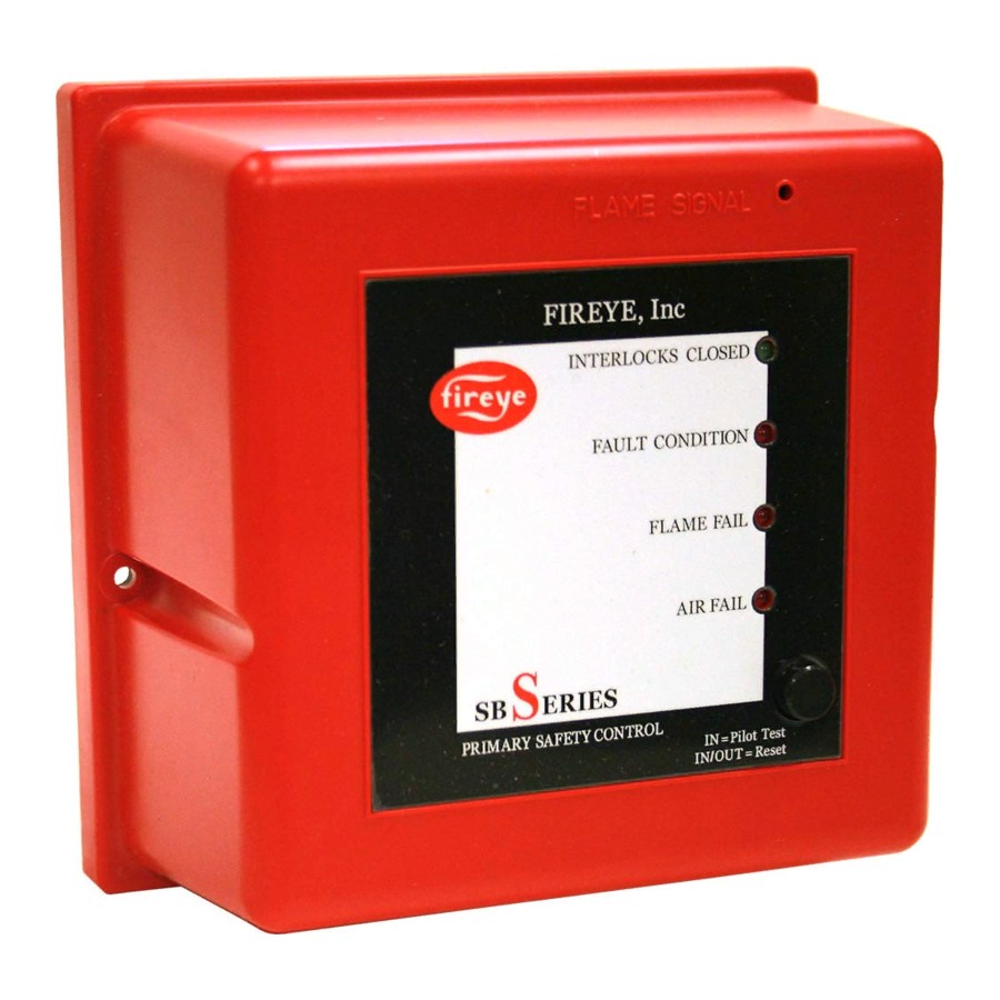
SB-2501
®
FIREYE
FLAME SAFEGUARD
CONTROLS
WARNING: Selection of this control for a particular application should be made by a com-
petent professional, licensed by a state or other government. Inappropriate application of
this product could result in an unsafe condition hazardous to life and property.
DESCRIPTION
1
Advertisement
Table of Contents

Related Manuals for Fireye SB Series


Summary of Contents for Fireye SB Series
- Page 1 SB-2501 ® FIREYE FLAME SAFEGUARD CONTROLS WARNING: Selection of this control for a particular application should be made by a com- petent professional, licensed by a state or other government. Inappropriate application of this product could result in an unsafe condition hazardous to life and property.
-
Page 2: Specifications
WARNING: This equipment generates and can radiate radio frequency energy, and if not installed and used in accordance with the instruction manual may cause interference to radio communications. It has been tested and found to comply with the limits for a Class A computing device pursuant to Subpart J of part 15 of FCC Rules, which are designed to pro- vide reasonable protection against such interference when operated in a commercial envi- ronment. -
Page 3: Ambient Temperature Limits
AMBIENT TEMPERATURE LIMITS Maximum Minimum Weight 140°F 60°C -40°F -40°C 3 lbs (1.4kg) UV Scanner, straight; SB49600-91 257°F 125°C -4° F -20° C 1 lb (.45kg) UV Scanner, 90 degree; SB49600-91 140°F 60°C -4° F -20° C 1 lb (.45kg) UV Scanner, sealed, NEMA4, SB20898 257°F 125°C... - Page 4 Flame Safeguard Controls Eclipse Part Number Fireye Part Number Description...
- Page 5 Flame Safeguard Controls Eclipse Part Number Fireye Part Number Description...
- Page 6 Flame Safeguard Controls Eclipse Part Number Fireye Part Number Description Flame Scanners and Accssories Eclipse Part Number Fireye Part Number Description...
- Page 7 Wiring Bases Displays DIMENSIONS FIGURE 1. Control Unit, all models FIREYE Inc. ¨ 5-1/4" Square 3" (133mm) (76mm) FIGURE 2. Bases, NO-PURGE and PURGE sequence models 7/32" Dia. (5.5mm) Mounting 5" 5" Holes (4) Square Square (127mm) (127mm) Knockouts (10) for 1/2"(13mm)
-
Page 8: Flame Scanners
FIGURE 3. MODULATION sequence model, SB49602-40 15/16" FIREYE Inc. ¨ (24mm) 6-3/4" (171mm) 1" (25mm) 8 A D S 2S 1 11 12 13 1-9/16" 3/8" (10mm) 3/16" (5mm) (40mm) 8-3/8" (213mm) 4-9/16" 116mm FIGURE 4. Remote Display SB20896 FLAME SCANNERS... - Page 9 INSTALLATION OF CONTROL, SCANNERS AND FLAME DETECTORS Wiring Base WARNING: Controls require safety limits utilizing isolated mechanical contacts. Electronic limit switches may cause erratic operation and should be avoided. Care must be taken to NOT route the high energy ignition wire in close proximity to the flame sensor wiring.
- Page 10 Terminal 4 - Ignition Wiring Low Fire Start Switch, (Terminal 3 –resistance through valve coil) Terminal V or D - Main Valve Closed Switch Input For purge and no purge models: For modulation models: Terminal D - High Purge Switch Input Terminal 1 - Remote Reset Remote Display Note:...
- Page 11 WARNING: Install a modulation sequence model into the modulation style base only; never plug into purge or no-purge bases. FIGURE 5. WIRING FOR NO PURGE MODELS 120 VAC 240 VAC 50/60 HZ 50/60 HZ 15 A On/Off Fuse Piloted Burner Pilot Ignition Main...
- Page 12 FIGURE 7. WIRING FOR DIRECT SPARK OF MAIN FLAME, NO PURGE MODELS & PURGE MODLES MAIN IGNITION Neutral Unit must be intermittent pilot, not interrupted FIGURE 8. WIRING FOR MODULATION MODULES 120 VAC 240 VAC 50/60 HZ 50/60 HZ On/Off 15 A.
- Page 13 FIGURE 10. WIRING FOR 120 VAC REMOTE DISPLAY MODULE 120 VAC Remote Display 120V 120V R1 R2 To 1 to 120 VAC Flame Signal PLUG 59-511-3 Test Jack To S2 FIGURE 11. TYPICAL CONNECTIONS FOR ALL MODELS UV/IR FLAME ROD Self Check UV SB49602-91 (Requires 59-504-010)
-
Page 14: Operation
OPERATION Introduction Standard Features Interlocks and Limit Switch Input (Terminal 7) Combustion Air Switch Input (Terminal 6) For PURGE and MODULATION sequence models Pre-Purge For PURGE sequence models: For MODULATION sequence models: SEQUENCE STEP INTERNAL CONTACTS FUNCTION Power Off 10 to 12 Power On, Limits Off 10 to 12 Purge to High Fire... -
Page 15: Dip Switch Selection
DIP SWITCH SELECTION Introduction DIP Switch Location DIP Switch Access No Purge DIP Switch Settings Modulation and Purge DIP Switch Settings NOTE: Flame Failure Response = 3 seconds +/- 0.5 seconds for all models. -
Page 16: Optional Features
Main Fuel Valve Closed Switch (Terminal V) For NO-PURGE and PURGE sequence models: Main Fuel Valve Closed / High Fire Purge Check (Terminal D) For MODULATION sequence models: Low Fire Start (Terminal 3 – impedance) For MODULATION sequence models: Pilot Test Mode Interrupted or Intermittent Pilot Spark, Pilot Flame &... -
Page 17: Lockout Condition
Manual Reset on Power Outage Remote Display System Errors and Lockout Conditions FAULT CONDITION LOCKOUT CONDITION (Illuminated by the red “Fault Condition” LED on Energizes the alarm output and deenergizes the gas the front cover) prevents gas ignition. The unit will valve and ignition outputs. - Page 18 Status Lights and Push-Button Interlocks Closed Air Failure For purge and modulation models: Fault Condition Flame Failure Low Fire High Fire Auto Test/Reset Flame Signal Note: Communication signals from the remote display are superimposed on the flame signal test jack. During a valid flame On condition these communication signals will appear to be negligible in comparison to the flame signal (if measuring the flame signal with a DVM for example).
- Page 19 TYPICAL SEQUENCE FOR NO-PURGE MODELS T erminal Function Contr ol Power Pilot Valve Outputs Ignition Main Valve Interlocks Inputs PO VC Flame Recycle 35 Seconds Check Permitted Main Pilot Firing Trial Cycle Trial 10 Sec TYPICAL SEQUENCE FOR PURGE MODELS T erminal Function Contr ol Power...
-
Page 20: Sensor Installation
SENSOR INSTALLATION WARNING: Incorrect sensor installation may cause the sensor to generate a false flame sig- nal, causing unburned fuel to collect in the combustion chamber. The result can be explo- sions, injuries and property damage. Be certain that the flame sensor detects only pilot and main flames, not glowing refractory, burner or ignition parts. - Page 21 WARRANTIES one year from the date of installation or 18 months from date of manufacture THE FOREGOING IS IN LIEU OF ALL OTHER WARRANTIES AND FIREYE MAKES NO WARRANTY OF MERCHANTABILITY OR ANY OTHER WARRANTY, EXPRESS OR IMPLIED. FIREYE SB-2501...
Need help?
Do you have a question about the SB Series and is the answer not in the manual?
Questions and answers