Table of Contents
Advertisement
MC-5000
MAY 10, 2017
FIREYE
MODULAR
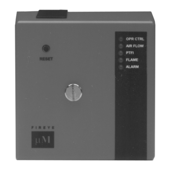
MicroM
Flame SAFEGUARD CONTROLS
APPROVED
WARNING: Selection of this control for a particular application should be made by a com-
petent professional, licensed by a state or other government agency. Inappropriate application
of this product could result in an unsafe condition hazardous to life and property.
DESCRIPTION
The Fireye MicroM Series Flame Safeguard Control is a compact, microprocessor based, modular
burner management system designed to provide automatic ignition and continuous flame monitoring
for commercial sizes of heating and process equipment firing any type of fuel.
The MicroM is designed to be backward compatible with existing TFM, UVM and M-Series II con-
trols. The MicroM MEC120 and MEC230 chassis with the appropriate MEP100, MEP200 and
Mep500 Series programmers provide operation similar to its predecessors and is usually directly
interchangeable. The MEC320 and MEC480 chassis with the appropriate MEP300, MEP400 and
MEP600 series programmers provide additional enhancements such as early spark termination, pilot
proving, and interrupted pilot.
The advantages of the MicroM are zero dependence on discrete components previously used for tim-
ing functions. The MicroM, through the use of micro-controller technology, incorporates smart diag-
nostic LED's, smart reset function for multi-burner applications, optional alpha-numeric display
output (ED510), and serial communications via a Modbus or E500 Communication Interface. The
MicroM system also provides additional amplifier selections. Along with the standard UV and
Flame Rod amplifiers are UV self-check, Infrared, Cadmium Sulfide and a dry contact amplifier for
use with the Fireye Phoenix scanner. All amplifiers are available with flame failure response times of
0.8 seconds or 3 seconds nominal (4 second maximum) and each provide a set of test jacks with a
uniform range of 0-10 VDC for the measurement of flame signal intensity.
A complete MicroM system includes the appropriate flame detector, plug-in amplifier and program-
mer modules which connect into a standard chassis and wiring base. Interchangeable programmer
and amplifier modules allow for complete versatility in selection of control function, timing and
flame scanning means. Functions such as relight, recycle, non-recycle, two stage capability, non-
recycle air flow, proof of air flow open at start, purge timing, early spark termination, pilot proving
and pilot cutoff are determined by the appropriate programmer module. Type of flame scanner (UV,
Repetitive UV Self-Check, Flame Rod, IR or Cadmium Sulfide or dry contact) and the flame failure
response time (FFRT) are determined by the amplifier module. Optional plug-in daughter boards
provide additional features such as remote reset, alpha-numeric display and serial communications.
The MicroM programmers are micro-controller based modules that control the sequence of opera-
tion and also interface with plug-in amplifiers, meter boards, display drivers and external communi-
cation devices. The programmers are available in an assortment of configurations necessary to
resolve the application requirement. Current families of programmers for use with the MEC120 and
1
Advertisement
Table of Contents

Related Manuals for Fireye MicroM Series


Summary of Contents for Fireye MicroM Series
- Page 1 Flame Rod amplifiers are UV self-check, Infrared, Cadmium Sulfide and a dry contact amplifier for use with the Fireye Phoenix scanner. All amplifiers are available with flame failure response times of 0.8 seconds or 3 seconds nominal (4 second maximum) and each provide a set of test jacks with a uniform range of 0-10 VDC for the measurement of flame signal intensity.
- Page 2 The modular MicroM controls use the same wiring base as the Fireye UVM, TFM and M- Series II controls and are designed to be interchangeable with most models with little or no rewiring. See INSTALLATION OF CONTROL, SCANNERS AND FLAME DETECTORS (page 8 and 47) for temperature and wiring requirements.
- Page 3 Table 2: LOAD RATINGS: All Ratings are 120V, 60 Hz Fireye Terminal Typical Load Maximum Rating @120V 60 Hz 125 VA pilot duty (solenoid valve) plus 3 or 4 Pilot valve(s) 250 VA (Transformer) Individual or combined Solenoid valve...
- Page 4 MOUNTING BASE 3/16” DIA. MOUNTING HOLES (4) KNOCKOUTS (12) FOR 1/2” CONDUIT 5 3/16” 4” μΜ 3/16” MOUNTING 1/2” HOLES 5 3/16” 5 5/16” 4” 1/2”’ 1.06” DIA. 2.58” 13/16” HEX 2 3/8” ”L” (27.0) (20.6) (60.3) (50.8) 1 3/16” (30) 15/16”...
- Page 5 WARNING: This equipment is a Class B digital apparatus which complies with the Radio Interference Regulations, CRC c.1374. CAUTION: Published load ratings assume that no control be required to handle inrush current more often than once in 15 seconds. The use of control switches, solenoids, relays, etc.
- Page 6 ORDERING INFORMATION MicroM Chassis Types (For use with MEP1XX, MEP2XX, and MEP5XX, includes dust cover) MEC120 120 VAC input with standard plug-in board. MEC120R 120 VAC input with remote reset capability. MEC120D 120 VAC input with alpha-numeric display interface to ED510. MEC120RD 120 VAC input with alpha-numeric display interface to ED510 and remote reset capability.
- Page 7 MicroM Programmer Models (For use with MEC320 and MEC 480 Chassis) MEP300 Relight operation, 10 sec. fixed PTFI, 5 sec.pilot proving period, 5 second MTFI. lockout on flame fail during PTFI, pilot proving and MTFI. Recycle on air flow open. No post purge. Reset on line voltage. MEP304 Non-recycle on flame fail, 5 sec.
- Page 8 Accessories ED510 Two line by 16 character, back lit LCD display with keypad. ED580-2, -4, -8 Remote display cable with RJ45 connection in 2, 4 or 8 foot long lengths. To be used with the appropriate daughter board. EC485 RS232 to RS485 converter with power supply and RJ12 jack.
- Page 9 90 degrees C. Good electrical wiring practice should be followed to ensure an adequate ground system. Refer to Fireye Service Note SN-100 separately and General Grounding Rules later in this document for grounding methods.
- Page 10 Terminals 3, 4, or 5. To replace the fuse, remove power from the system and using a small screwdriver or similar tool, install a Fireye replace- ment fuse (P/N 23-197).
- Page 11 FIGURE 2. Replaceable Fuse Location PROGRAMMER DIPSWITCH SETTINGS NOTE: The dipswitch settings become permanently stored within the programmer’s eeprom memory after 8 hours of continuous electrical operation. The first 8 hours of continuous operation is determined from the value of system hours being accu- mulated by the MicroM.
- Page 12 Once the switches are set, they become permanently stored after 8 hours of continuous operation or they can be manually set through the use of the optional ED510 display. Refer to the section using the optional ED510 display for detailed information. Where applicable, each MicroM programmer is shipped with dip-switch 6 set to non-recycle on flame fail, dipswitch 4 set to 5 second PTFI time, and dipswitches 1 &...
- Page 13 PTFI: This LED is illuminated only during the pilot trial for ignition period and the stabilization period when so equipped. Flame: This LED is on whenever a flame signal is detected, and the control is not in a locked out state.
- Page 14 DIAGNOSTIC MESSAGES - TROUBLESHOOTING GUIDE POSSIBLE CAUSE SOLUTION Check Programmer Voltage on Terminal 5 at improper time. Inspect wiring to main fuel valve Welded watchdog relay Replace MEC chassis Internal diagnostic failure Replace MEP programmer Check Chassis Voltage on Terminal 3 or 4 at improper time. Inspect wiring to pilot valve and igniter.
- Page 15 Safety Shutdown In the event pilot flame is not detected at the end of the 10 second PTFI period, the pilot gas valve and spark ignition are de-energized. A safety lockout occurs which de-energizes the burner motor and energizes the lockout alarm relay circuit, lighting the Alarm LED, 15 seconds after the safety lockout occurs.
- Page 16 following a post purge of 30 seconds and a safe start check. Failure to ignition spark on the second attempt results in safety lockout. MEP100P The MEP100P programmers provides a fixed 15 second post purge period upon detection of the operating Control (1-7) or Air Flow switch (7-6) opening.
- Page 17 If non-recycle operation is selected, in the event of a main flame failure, power is removed from Ter- minal 3 and Terminal 5. The control will enter a forced post purge period of 15 seconds, after which the Alarm LED is illuminated and the alarm relay is energized putting power on Terminal A. The MEP230H programmer operates the same as the MEP230 with the exception of an additional 8 second pilot stabilization.
- Page 18 TYPE MEP236 PROGRAMMING SEQUENCE INTERLOCK FIRING PURGE L1/7 L1/7 AIR FLOW PERIOD COMPLETE PROVEN SELECTABLE POST PURGE SELECTABLE PILOT PURGE SELECTABLE PTFI MFSP* 6 SEC 5 OR10 SEC IGNITER MAIN VALVE *MAIN FLAME STABILIZATION PERIOD Terminal #5 is energized 3 seconds after the flame is detected. Selectable Recycle/Non-Recycle operation on loss of flame after flame is proven.
- Page 19 A “run-check” switch is also provided to assist in testing size, position and stabilization of pilot in conjunction with the flame detector, For the MEP560 and MEP562, after pilot flame is detected, the control enters an 8 second pilot stabi- lization period with Terminal 3 and Terminal 4 energized.
- Page 20 TYPE MEP562 PROGRAMMING SEQUENCE INTERLOCK FIRING PURGE L1/7 L1/7 AIR FLOW PERIOD COMPLETE PROVEN SELECTABLE POST PURGE SELECTABLE PURGE PTFI STABLIZATION 5 OR10 SEC PERIOD 8 SEC MTFI 10 SEC Pilot stabilization timing begins as soon as flame is proven. Lockout on loss of air flow (interlock circuit) after flame is proven.
- Page 21 TYPE MEP304 PROGRAMMING SEQUENCE INTERLOCK FIRING PURGE L1/7 L1/7 AIR FLOW PERIOD COMPLETE PROVEN POST PURGE 5 SECOND PURGE 5 SEC 10 SEC 10 SEC INTERRUPTED PILOT PTFI MTFI PILOT PROVING 0 Second post purge on operating control open. 15 Second post purge on flame fail. Non-recycle operation on flame fail.
- Page 22 TYPE MEP397 PROGRAMMING SEQUENCE INTERLOCK FIRING PURGE L1/7 L1/7 AIR FLOW PERIOD COMPLETE PROVEN POST PURGE 1 5 SECOND PURGE 5 SEC 7 SEC 5 SEC INTERRUPTED PILOT PTFI MTFI PILOT PROVING 0 Second post purge on operating control open. 15 Second post purge of flame fail during PTFI, Proving and MTFI.
- Page 23 TYPE MEP697 PROGRAMMING SEQUENCE FIRING INTERLOCK PURGE PERIOD L1/7 L1/7 AIR FLOW COMPLETE (AUTO) PROVEN SELECTABLE POST PURGE SELECTABLE PURGE 5 SEC 5/10 SEC 10 SEC INTERRUPTED PILOT SELECTABLE MTFI PILOT PROVING PTFI MODULATE CONTACTS Lockout on flame fail. Lockout on air flow switch opening while main flame energized.
- Page 24 Function Any MicroM chassis type with the appropriate plug-in board installed provides remote reset capabil- ities in the event of a lockout condition. A remote reset switch consists of a dry contact such as a remote momentary push-button wired to the two (2) terminals located on the plug-in board as shown in Figure 5.
- Page 25 MicroM will reset from the lockout state only. This is especially useful where, through the use of remote reset daughter boards, all reset inputs can be connected together to a common reset pushbut- ton or intelligent device (PLC). If the push button is depressed as described above it will only cause the unit that is in lockout to reset and not effect any other units.
- Page 26 OPERATING STATUS TIMING (Standby, Purge, PTFI, (During Purge or PTFI) OR FLAME SIGNAL STRENGTH Auto, etc.) (During PTFI, MTFI, or Auto) PURGE 00:05 STARTING BURNER ADDITIONAL INFORMATION ON OPERATING STATUS (Flame Signal Strength, Cause of current Lockout, etc.) OR ARROW displayed when BURNER HISTORY (SCRL key required) MODE key is required to...
- Page 27 LOCKOUT HISTORY The sub-menu “LOCKOUT HISTORY” will display the last six (6) lockouts, along with the burner cycle and burner hour when the lockout occurred. When the MODE key is pressed, the screen will display the most recent lockout condition and the number of that lockout (e.g. LO #127 represents the 127th lockout of that control).
- Page 28 UNIT ADDRESS 00 SCRL PRESS RESET TO Force storage of dipswitch settings before 8 hours time-out. ACCEPT SETTINGS MODE AUTO Mode key returns to normal run message. SYSTEM INFO The sub-menu “SYSTEM INFO” allows the user to review information pertaining to the operation of the control (e.g.
- Page 29 The format of the data is 4800, N, 8, 1 meaning 4800 baud, no parity, and 1 stop bit. Below is a table of currently available messages provided by the MicroM programmers, followed by a description where necessary. MESSAGE WORDS RESPONSE VALUE...
- Page 30 Message 26 returns the current operating status as well as stored burner hours and burner cycles as a snapshot of the entire MicroM system. When all 9 words are requested, the data returned consists of STATUS, MSGN, FLAME, INPUTS, OUTPUTS, BNRMINS, and BNRCYCS. The MSGN being transmitted is a numerical value and must be interpreted by the communicating device, which actually is an advantage since this can be made to be whatever message text the end user wants.
- Page 31 It is suggested that repeated polling interval not be less than 200 mSec per request. Requesting data such as burner minutes, system minutes and burner cycles be kept at a minimum due to the amount of processing time required to gather that data. Table 1: Logic Dispatch LOGIC DISPATCHER VALUE...
- Page 32 Table 2: Program Module Identification Programmer Module Identifier MEP100 0H, 01H MEP101 0H, 02H MEP102 0H, 03H MEP103 0H, 04H MEP100P 0H, 05H MEP109 0H, 06H MEP130 0H, 08H MEP104 0H, 09H MEP105 0H, 0AH MEP106 0H, 0BH MEP107 0H, 0CH MEP108 0H, 0DH...
- Page 33 Table 3: Message Description MicroM Message L1-7 OPEN FALSE FLAME STARTING BURNER INTRLCK OPEN LOCKOUT LINE FREQUENCY NOISE DETECTED LOCKOUT FLAME FAIL - PTFI UNIT ADDRESS MTFI IGNITION TIMING FLAME SIGNAL CYCLE COMPLETE LOCKOUT AMPLIFIER HIGH COUNT FAIL LOCKOUT FLAME FAIL – MTFI LOCKOUT FALSE FLAME –...
- Page 34 line of the display. Pressing and releasing the RESET key will cause the address to increment. The address after 31 is 0. The second method is to use the local reset located on the plug-in board. It is first necessary to open the operating control (L1-7) to have the MicroM in the IDLE or STANDBY position.
- Page 35 Use of Test Meter (All Controls) Testing the Fireye MicroM Controls requires the use of a test AC/DC multimeter, with a minimum 1000 ohm/volt AC scale and 20,000 ohm/volt DC scale. With the test meter on the DC scale, and the test meter leads inserted into the test jacks on the ampli- fier (Red for positive (+) polarity, Black for minus (-) polarity), a DC voltage reading of 4.0 to 10...
- Page 36 When using a flame rectification amplifier, a micro-ammeter may be connected in series with the wire to Terminal S2. Normal flame will produce a meter reading between 4 and 10 micro-amps. With the test meter on the AC scale, line and load voltages may be measured at the identified test points on the chassis.
- Page 37 Manually shut off all fuel and observe the loss of flame signal on the test meter. If flame signal does not reduce to zero within the flame failure response time of the control (FFRT determined by the selection of the amplifier), verify the UV flame detector is not actu- ated by the ignition spark.
- Page 38 NO HEAT MicroM SERVICE GUIDE O.C. ON TEST JACKS ALARM BLINKING SITUATION #1 NORMAL LOCKOUT ALL TYPES 4-10 VDC INSTALL DC VOLTMETER AMPLIFIER MODULE IN TEST JACKS MP100 4-7 SECONDS SHUT FUEL MP230 PREPURGE DELAY TIME SUPPLY COCK FLAME WAIT LED COME PROPER...
- Page 39 ...
- Page 40 MEUVS1; 260 VAC across S1, S2 with MERT4 and MERT1. CAUTION: Control wiring procedures which deviate from those shown in the diagrams may bypass safety functions designed in the control. Check with the Fireye Representative before deviating from the recommended wiring diagrams.
- Page 41 FIGURE 7. WIRING ARRANGEMENT FOR PILOT IGNITED BURNERS AND PROVISION FOR MAIN FLAME STABILIZATION USING MEP236 SERIES PROGRAMMERS AIR FLOW OPERATING INTERLOCK CONTROLS FLAME SCANNER FLAME ONLY (WATCHDOG) FLAME AMPLIFIER 120VAC 50/60Hz KF-1 INTERMITTENT SPARK MAIN VALVE ALARM BLOWER MOTOR IGNITION PILOT VALVE CONTACTOR...
- Page 42 FIGURE 9. WIRING ARRANGEMENT FOR PILOT IGNITED BURNERS AND INTERRUPTED PILOT USING MEP500 SERIES PROGRAMMERS AIR FLOW OPERATING INTERLOCK CONTROL FLAME SCANNER FLAME ONLY (WATCHDOG) FLAME AMPLIFIER 120VAC 50/60Hz KF-1 INTERMITTENT INTERRUPTED MAIN FUEL ALARM BLOWER MOTER GAS PILOT VALVE PILOT GAS VALVE VALVE AND IGNITION...
- Page 43 FIGURE 11. WIRING ARRANGEMENT FOR FLAME SWITCHES USING MEP100 PROGRAMMERS ENABLE/DISABLE INPUT FLAME SCANNER FLAME ONLY (WATCHDOG) FLAME AMPLIFIER 120VAC 50/60Hz KF-2 KF-1 ISOLATED SWITCHED OUTPUTS OUTPUTS REFER TO LOAD RATING VOLTAGE SOURCE * FUSE F1 CAN BE REMOVED NOTE: Air Flow LED will blink while flame is detected and KF relay is energized.
- Page 44 AIR FLOW SWITCH MULTIPLE BURNER SYSTEMS UTILIZING SEMI-AUTOMATIC OPERATION INCORPORATE THE FIREYE MODULAR MI- CROM CONTROLS IN A CASCADING SEQUENCE WHEN PILOT #1 IS PROVEN. TRIAL FOR IGNITION FOR PILOT #2 BEGINS. WHEN ALL PILOTS ARE PROVEN THE SAFETY SHUTOFF VALVE MAY BE MANUALLY OPENED. FLAME FAILURE OF ANY BURNER WILL TRIP THE MAIN FUEL VALVE AND SOUND ALARM.
- Page 45 FIGURE 14. BACKWARD COMPATIBLE WIRING USING MEP100 AND MEP200 SERIES PROGRAMMERS (PILOT IGNITED BURNERS). AIR FLOW OPERATING INTERLOCK CONTROL FLAME SCANNER FLAME ONLY (WATCHDOG) FLAME AMPLIFIER 120VAC 50/60Hz KF-2 KF-1 INTERMITTENT SPARK MAIN VALVE ALARM BLOWER MOTOR IGNITION PILOT VALVE CONTACTOR For intermittent ignition, connect to terminal 3 Combined current from Terminal 8 must not exceed 9.8 Amps...
- Page 46 When the ED510 is to be remotely mounted on the front of the control panel, the ED580 cable must contain a ferrite core, currently supplied by Fireye with the cable. The cable end with the ferrite core must be mounted at the control end. High frequency currents flow more to the surface of the conduc- tor.
- Page 47 Source end is defined as the originating end of the communication system Care must be taken not to route communication cables in close proximity to any starter motor con- tactors located in the control panel or across any high voltage ignition wires. Refer to Fireye bulletin E-8002 for proper installation.
- Page 48 Use 1/2" x 1 1/2" pipe nipple between UV1A Scanner and the coupling. Use 3/8" pipe nipple and a 1/2" x 3/8" bushing on UV2 installations. Request the assistance of any Fireye field office for recommendations of a proper scanner instal- lation on a non-standard application.
- Page 49 OPERATION — 45UV5 SELF-CHECKING UV SCANNER Self-checking ultraviolet scanners should be used in applications where burner firing operation is continuous or where the burner is on for long periods of time without recycling. In addition, ultra- violet self-checking systems are mandatory in some locations. The operation of this type of system consists of maintaining the flame scanning capability at all times while also proving that the ultraviolet tube is firing properly.
- Page 50 Use 6" to 8" length of pipe between scanner and hot furnace front plate. Use insulating tube (P/N 35-69) on the end of the iron pipe. Force air into sighting tube. Use Fireye Sealing Union (P/N 60-801). Make sure sighting tube does not extend more than halfway into refractory wall.
- Page 51 INSTALLATION - 69NDl FLAME ROD The 69NDl flame rod proves a gas pilot flame and/or main gas flame. It is a spark plug type unit con- sisting of 1/2" NPT mount, a KANTHAL flame rod, a glazed porcelain insulating rod holder and a spark plug connector for making electrical connections.
- Page 52 MAINTENANCE Type 48PT2 Infrared and Type UV1A, UV2 and 45UV5 Ultraviolet Scanners The viewing area of the scanner must be kept clean. Even a small amount of contamination will reduce the flame signal reaching the detector by a measurable amount. Wipe the viewing area rou- tinely using a soft cloth dampened with concentrated detergent.
- Page 53 FIGURE 16. Mounting 45UV5 Scanner #60-1664 #60-1664 1” SWIVEL MOUNT AIR ENTRY 1” SWIVEL MOUNT APERTURE (PURGE AND #53-121 #35-127 COOLING) HEAT INSULATING NIPPLE 2.75” (70) RETAINER STANDARD MOUNTING #34-181 FOR TYPES OF SCANNERS #60-1664 AIR/ENTRY PURGE AIR ENTRY 1”...
- Page 54 FIGURE 18. Mounting UV1A/UV1B Scanners BURNER FRONT PLATE 1/2” UV SCANNER 1/2” SWIVEL MOUNT 1/2” SWIVEL MOUNT TYPE UV-1A #60-302 #60-302 HEAT INSULATOR #35-69 1/2” NIPPLE 1/2” NIPPLE 2” 2” (51) (51) STANDARD MOUNTING MOUNTING WITH HEAT INSULATING NIPPLE 1/2”...
- Page 55 M-SERIES TO M-SERIES II TO MICROM CROSS REFERENCE LISTING M-SERIES M-SERIES II REPLACEMENT MODULES MicroM REPLACEMENT MODULES Part Chassis Amplifier Programme Programmer Chassis Amplifier Programmer Programmer Number Dipswitch #8 Dipswitch #6 UVM1D MC120 MAUV1T MP100 MEC120 MEUV1 MEP100 UVM1F MC120 MAUV1 MP100...
- Page 56 FIGURE 19. Red jumper wire Red wire...
- Page 57 ...
- Page 58 Fireye warranty, as stated in its General Terms and Conditions of Sale, pertains only to the Fireye products and not to any other equipment or to the com- bined system or its overall performance.
Need help?
Do you have a question about the MicroM Series and is the answer not in the manual?
Questions and answers