Table of Contents
Advertisement
Quick Links
®
E-2101
MAY 12, 2011
FIREYE E210/211
FLAME-MONITOR™
Microprocessor-Based
Burner Management Control
with
Message Center and
Self-Diagnostics
DESCRIPTION
®
™
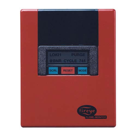
The FIREYE
FLAME-MONITOR
control is a microprocessor based burner management control
with self-diagnostics, non-volatile memory and a library of informational messages. These messages
scroll out on the ED510 Display Module, providing operator status and failure mode information. The
system provides the proper burner sequencing and monitoring of the flame on automatic burners, sin-
gle or dual fuel fired burners, direct spark or pilot ignited burners and on/off or modulating burners.
Inputs for all burner interlocks are provided: i.e. recycling limit and operating controls, non-recycling
running interlocks, purge air flow switch and firing rate motor end switches. The FLAME-MONITOR
control programs the burner/blower motor, ignition transformer, pilot and main valve for proper and
safe burner operation to meet specifications of approval authorities.
On a safety shutdown, the ED510 message center will advise the operator that the control is in
"ALARM" and scroll a message indicating the cause. Interchangeable flame amplifier and program-
mer modules allow for complete versatility in the selection of flame detectors and display language
(English, French, Dutch, German, Spanish or Swedish).
Several operational characteristics of the EP113 programmer modules (with Engineering code 21 or
later) are determined by six dipswitches located on the side of the programmer. These characteristics
include non-recycle or recycle operation (3-P circuit), interrupted or intermittent operation of terminal
5, extended purge timing, and the option to enable or disable the requirement that the 3-P running
interlock circuit is proven open at the start of the operating cycle.
Additional accessories include an expansion module. The E320 expansion module for the FIREYE
FLAME-MONITOR control adds the capability of individually displaying any malfunction for an
additional sixteen interlock switches. The module provides first-out annunciation of all interlocks.
Remote reset — see Bulletin E-8002
Expansion Module — see Bulletin E-3201
1
Advertisement
Table of Contents

Subscribe to Our Youtube Channel
Related Manuals for Fireye FLAME-MONITOR E210


Summary of Contents for Fireye FLAME-MONITOR E210
- Page 1 5, extended purge timing, and the option to enable or disable the requirement that the 3-P running interlock circuit is proven open at the start of the operating cycle. Additional accessories include an expansion module. The E320 expansion module for the FIREYE FLAME-MONITOR control adds the capability of individually displaying any malfunction for an additional sixteen interlock switches.
-
Page 2: Design Features
APPLICATION • For single or dual fired burners, pilot ignited or direct ignited continuous duty. • One basic model meets various European standards. • ED510 message center indicating in English, French, Dutch, Spanish, or German program sequence and reasons for alarm burner shutdown •... - Page 3 ® Supply voltage and electrical ratings Supply Voltage: EB720 220V (Europe) (min. 187V., max. 242V.) 240V (U.K.) (min. 204V. max. 264V.) EB721 110V (min. 94V. max. 132V.) Frequency: 50/60Hz Power consumption: Operating: 25 VA Standby: 13 VA Typical timings – Timing chart Prepurge time: 1 sec., 15 sec., 30 sec., 60 sec., 2 min., 5 min., 10 min., 15 min., (selectable by dipswitch on program module).
- Page 4 FLAME-MONITOR Ordering Information E210 OR E211 FLAME-MONITOR (ONE REQUIRED) ED510 DISPLAY MODULE ONE REQUIRED E210 CONSISTS OF: E211 CONSISTS OF: EB720 CHASSIS EB721 EC600 DUST COVER EC600 48-1836 MOUNTING SCREW 48-1836 AMPLIFIER MODULE (ONE REQUIRED) WIRING BASE (ONE REQUIRED) E1R3 60-1386-2 EUV1...
- Page 5 ® APPROVALS E210, E211, EP113D, EP113E, EP113F, EP113NL, EP113NR, EUV1, EUVS4, EIR3 Gas Appliances Gas Appliance Directive: 90/396/EEC Low Votage Directive: 73/23/EEC EMC Directive: 89/336/EEC GASTEC: CG-63AP2200 (EN298, October 1993; EN230, November 1990) Classification: F/I or T/L or C/L/J/B Apave: E210, EP113F, EUV1, EUVS4, EIR3 FLAME SCANNERS INFRARED...
-
Page 6: Accessories And Spare Parts
ACCESSORIES AND SPARE PARTS DESCRIPTION TYPE Firetron cell 4-263-1 48PT2 UV tube 4-314 45UV3, 45UV5 Lens 61-436 48PT2 Quartz lens (3/4”) 46-56 45UV3 Quartz lens (1”) 46-38 45UV5 Union coupling – with glass lens 60-801 48PT2 – with quartz glass 60-1257 UV1A –... - Page 7 ® DIPSWITCH #1 - NON-RECYCLE OR RECYCLE OPERATION: Dipswitch #1 determines if the control will lockout (dipswitch 1 is Down) or recycle (dipswitch 1 is Up) when the running interlock circuit (3-P) is opened during the firing cycle or following a flame failure after the control has released to modulation (following completion of MTFI).
-
Page 8: Unit Address
cuit does not open, the control will lockout. The programmers are shipped with this option enabled (switch 6 is in Down position). RJ45 STYLE CONNECTOR RJ12 STYLE CONNECTORS CHECK-RUN SWITCH TO ED510 DISPLAY TO E500 COUMMUNICATION INTERFACE PROGRAMMER AND DISPLAY MODULE COMPATIBILITY Two display modules are available for the FLAME-MONITOR control system (P/N's ED500 ED510). -
Page 9: Operation
Maximum address is 15. Then the address will roll over to 00. OPERATION The Fireye Flame-Monitor control provides proper burner sequencing and flame monitoring on auto- matic burners. It also provides the operator a status readout as well as diagnostic information. It has a number of unique messages which are simple to understand and interpret. - Page 10 The prepurge is initiated when the high fire interlock (purge air flow interlock) is closed within 180 seconds, confirming that the firing rate motor reached its high fire position. The supervised prepurge time is 30 seconds. When the prepurge is completed, the firing rate motor is driven towards the low-fire position, to be reached within 180 seconds.
-
Page 11: Sequence Flow Chart
** PURGE TIME: 1 SEC. TO 15 MIN. SELECTABLE BY DIPSWITCHES #3, #4 AND #5. ALARM–LOCKOUT CONDITION The FIREYE Flame-Monitor control will lockout under the following conditions: At any time — Excessive current load at either terminal X, 5, 6, or 7 —... - Page 12 — Opening of non recycling interlocks (3-P) — Flame failure CIRCUIT DIAGRAM — FLAME MONITOR™ E210/E211 NON-RECYCLING RECYCLING INTERLOCKS RUNNING INTERLOCKS SCANNER TERMINALS L1/L 220V. Europe 240V in U.K. FIREYE FLAME MONITOR E210/211 (50-60Hz) L2/N AUTO HIGH LOW FIRE PURGE AIR FIRE FIRE START...
- Page 13 ® MESSAGES There are two types of messages shown on the ED510 message center: Normal program start-up and stop messages. Alarm - Lockout messages RUN MESSAGES DESCRIPTION The burner has stopped. It is waiting for a demand for heat to burner sequence STANDBY again.
- Page 14 Alarm messages related to the SAFETY CIRCUIT These messages scroll on the display when an abnormal status of the safety circuit is confirmed. After the post-purge time of 10 seconds, the control trips (lockout). The message remains until the control is reset (even after a power failure).
- Page 15 ® Flame failure during burner operation. ALARM AUTO FLAME FAILURE Alarm messages related to the FIELD CONDITIONS These messages scroll on the display when an improper field condition occurs. After the post-purge time of 10 seconds, the control trips (lockout).The message remains until the control is reset (even after a power failure).
- Page 16 HISTORICAL INFORMATION /SYSTEM SUB-MENUS At any time the control is powered, the SCRL key will scroll through and display the total number of burner cycles, burner lockouts, and system hours on the bottom line of the ED510 display. The top line will continue to show the current run mode of the control (e.g.
-
Page 17: Alarm History
® ALARM HISTORY The sub-menu LOCKOUT HISTORY will display the last six (6) lockouts, along with the burner cycle and burner hour when the lockout occurred. When the MODE key is pressed, the screen will display the most recent lockout condition and the number of that lockout (e.g. LO #127 represents the 127th lockout of that control). - Page 18 Press the Mode key and the screen displays: E320 TERM #22 LOW OIL TEMPERATURE or programmed message. Press the Scroll key and the screen displays: E320 TERM #24 LOW OIL PRESSURE or programmed message. To change the message, press and hold the Reset key for one (1) second. When the Reset key is released, the screen displays: MDFY TERM #24 LOW OIL PRESSURE...
-
Page 19: Program Setup
® USER PROGRAMMED E320 MESSAGES In addition to selecting the lockout alarm messages for the E320 Expansion Module from a menu selection via the ED510 display, the user can also program any message (up to 40 characters in length) for the individual terminals of the E320 using a dumb terminal (or PC with communication software) and the appropriate interface cables. -
Page 20: System Info
SYSTEM INFO The sub-menu SYSTEM INFO allows the user to review information pertaining to the operation of the control (e.g. average main flame signal strength, status of the high fire and low fire end switches, etc.). This information can be very helpful when setting the damper linkages on the firing rate motor. The MODE key is used to enter the SYSTEM INFO sub-menu, and the SCRL key is used to advance through the sub-menu. -
Page 21: Installation Instructions
Do not force the module into position. INSTALLING PROGRAMMER MODULE Fireye FLAME-MONITOR Programmer Modules are used with Fireye Series EB720 or EB721 base chassis. To install, simply insert the module into the second slot on the control (marked “Programmer Module” on the side of the chassis. -
Page 22: Installing The Control
INSTALLING THE DISPLAY MODULE Slide the bottom of the ED510 display onto the two (2) mounting tabs on the face of the EP113 programmer. Tilt the ED510 display towards the cover until the mounting tab on top of the ED510 display snaps into position into the opening on the face of the EP113 programmer. -
Page 23: Scanner Installation
• Mounting with heat insulating nipple • Mounting in case of excessive furnace or windbox pressure Note: 1/2” nipples and l/2” TEE pieces are not available from Fireye; these must be purchased locally. Ultra-violet scanner installation • Locate the scanner as close as possible to the flame. - Page 24 — Standard mounting — High temperature mounting — High pressure/temperature mounting Note: 1“TEE pieces are not available from Fireye; they must be purchased locally. SCANNER WIRING Like other FIREYE controls, the FIREYE FLAME MONITOR is protected against short-circuited scanner input terminals. Following recommendations apply for scanner control wiring: •...
- Page 25 ® MOUNTING UV1A/UV1B SCANNERS BURNER FRONT PLATE 1/2'' SWIVEL MOUNT HEAT INSULATOR 1/2'' SWIVEL MOUNT #60-302 #35-69 1/2'' –UV SCANNER #60-302 TYPE UV1A or UV1B (6) 1/2'' NIPPLE 1/2'' NIPPLE Ø50 Ø50 STANDARD MOUNTING MOUNTING WITH HEAT INSULATING NIPPLE AIR ENTRY (PURGE 1/2'' SWIVEL MOUNT AND COOLING) #60-302...
- Page 26 SELECTION OF APPROPRIATE FLAME DETECTOR MODEL 1007 INFRARED ULTRA-VIOLET ULTRA-VIOLET DETECTOR DETECTOR SELF-CHECK DETECTOR Oil Firing Gas Firing Strong Refectory Continuous Firing Intermittent Firing Infrared detectors can be used with almost any single burner application although some difficulty may be encountered with small gas pilots which have a limited infrared output. The infrared radia- tion passes readily through normal combustion products and dirty surfaces which makes them very reliable in single burner applications.
-
Page 27: Maintenance
Contacts There are no accessible contacts in the Fireye Flame Monitor controls. Where contacts are used, their design assures long trouble-free life, when the load circuits are maintained within the published load ratings. -
Page 28: Component Dimensions
COMPONENT DIMENSIONS 5 11/16 WIRING BASE CONTROL WITH COVER AND WIRING BASE (144.5) 2 7/16 MOUNTING HOLES (61.9) 3 5/8 (92) 1 7/8 KNOCKOUTS FOR 5 1/4 (48) 1/2 CONDUIT (7) (133) 7 9/32 7 9/32 5 3/4 (185) (146) (177.8) 3 7/32... - Page 29 ®...
- Page 30 ...
- Page 31 ®...
- Page 32 Fireye warranty, as stated in its General Terms and Conditions of Sale, pertains only to the Fireye products and not to any other equipment or to the combined system or its overall performance.
Need help?
Do you have a question about the FLAME-MONITOR E210 and is the answer not in the manual?
Questions and answers