Table of Contents
Advertisement
®
BL-1001
December 17, 2008
®
YB110/YB230 FIREYE
BurnerLogiX
™
MICROPROCESSOR-BASED
INTEGRATED BURNER
MANAGEMENT CONTROL
APPROVED
DESCRIPTION
®
The Fireye
BurnerLogix™ System is a microprocessor based burner management control system
designed to provide the proper burner sequencing, ignition and flame monitoring protection on auto-
matically ignited oil, gas, and combination fuel burners. In conjunction with limit and operating con-
trols, it programs the burner/blower motor, ignition and fuel valves to provide for proper and safe
burner operation. Through SMART LED'S, the control provides current operating status and lockout
information in the event of a safety shutdown. Optional VFD and LCD displays are available that
may be either plugged in or mounted remotely to give full language descriptors of current status and
diagnostic lockout information. Refer to BurnerLogix PROGRAMMER SELECTION later in this
document for the various combinations of programmer and display modules.
A complete BurnerLogix system includes the YB110 (YB230) chassis equipped with the type of
flame amplifier required for the application, appropriate flame detector, plug-in programmer mod-
ule, wiring base and optional alpha-numeric display. Interchangeable programmer modules allow for
complete versatility in selection of function, timing and flame failure response times.
The optional alpha-numeric display is made up of 2 lines by 16 characters per line and is available in
either vacuum fluorescent or liquid crystal formats. The advantage of VFD is high brightness and
extended temperature range to –40°F. Both displays contain a fully functional keypad allowing the
user to easily scroll through the various menus to view the current operating status, review program-
mer configuration, and lockout history. An advantage of the BurnerLogix control family is the abil-
ity to set many of the operating parameters associated with proper and reliable burner operation
allowing inventory of various programmer types to be kept to a minimum.
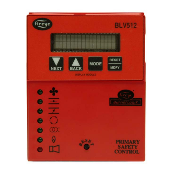
The YB110 (YB230) is a chassis/flame amplifier module complete with mounting screws and blank
display module. The display module (BLV512 or BLL510), if required, must be ordered separately.
Interchangeable YP programmer modules allow for complete versatility in selection of control func-
tion, timing, and flame scanning means. Functions such as pre-purge time, recycling or non-recy-
cling interlocks, high fire proving interlock, and trial for ignition timing of the pilot and main flame
are determined by the programmer module. The BurnerLogix system can be used with ultra-violet,
auto-check infrared, flame rod, self-check ultra-violet flame scanners or direct coupled integrated
scanners by choosing the proper chassis/flame amplifier module.
1
Advertisement
Table of Contents

Related Manuals for Fireye YB110


Summary of Contents for Fireye YB110
- Page 1 Refer to BurnerLogix PROGRAMMER SELECTION later in this document for the various combinations of programmer and display modules. A complete BurnerLogix system includes the YB110 (YB230) chassis equipped with the type of flame amplifier required for the application, appropriate flame detector, plug-in programmer mod- ule, wiring base and optional alpha-numeric display.
- Page 2 £ Wiring bases for the BurnerLogix control are available pre-wired with 4 foot lead wires color coded and marked for easy installation or with an integral terminal block capable of a accepting up to 2 X 14 AWG wires. The wiring base terminal block is available with knockouts for conduit or open ended for cabinet mounting.
-
Page 3: Table Of Contents
® TABLE OF CONTENTS BURNERLOGIX SPECIFICATIONS ............. . PART NUMBERS AND APPROVALS . -
Page 4: Burnerlogix Specifications
£ BURNERLOGIX SPECIFICATIONS Supply Voltage: YB110 120 VAC (+10%, -15%) 50/60 Hz YB230 230 VAC (+10%, -15%) 50/60 Hz Power Consumption: 25 VA Temperature Rating: -40°C (-40°F) to +60°C (140°F) Protection Category: YB110 (YB230) control NEMA 1 (IP01) Display, remote mounted NEMA 4X (IP66) Unit Dimensions: Wiring base 60-2810-1 - 4.0"... - Page 5 ® Combination of fuel and igniter terminals Combination No. Pilot Fuel Main Ignition Delayed Valve Trm 6 Trm 7 Trm 5 Trm W No Load No Load No Load No Load No Load No Load No Load No Load No Load No Load No Load Composition of each combination...
- Page 6 £ APPROVALS Underwriters Laboratories Inc.: MCCZ File MP1537 Controls, Primary Safety - Listed MCCZ2 File MP1537 Controls, Primary Safety - Component MCCZ7 File MP1537 Controls, Primary Safety Certified for Canada MCCZ8 File MP1537 Controls, Primary Safety Certified for Canada - Component Approved Factory Mutual: Acceptable by:...
-
Page 7: Part Numbers And Approvals
® PART NUMBERS AND APPROVALS Table 1: Agency Approvals BurnerLogix Chassis/Flame Amp. Module APPROVED YB110UV YB110UVSC YB110IR YB110IR2 YB110FR YB110DC YB230UV YB230UVSC YB230IR BurnerLogix Programmer Module YP100 YP102 YP138 YP118 YP200 YP202 YP300 YP302 YP113 BurnerLogix Displays BLV512 BLL510 BurnerLogix Wiring Bases 60-2810-1 60-2812-1 60-2814-1... -
Page 8: Ordering Information
£ WARNING: This equipment generates and can radiate radio frequency energy, and if not installed and used in accordance with the instruction manual may cause interference to radio communications. It has been tested and found to comply with the limits for a Class A computing device pursuant to Subpart J of part 15 of FCC Rules, which are designed to provide reasonable protection against such interference when operated in a commercial environment. - Page 9 Alarm annunciation system using wireless technology IT1000 PPC6000 Parallel Positioning System 61-5745-3 Shutter drive assembly for redundant self-check scanners SCANNER SELECTION FIREYE P/N DESCRIPTION USE WITH CHASSIS BULLETIN 48PT2-1003 Infrared 1/2" straight mount 96"(2438mm) flex conduit 48PT2-9003 Infrared 1/2" straight mount 96" (2438mm) flex conduit...
- Page 10 £ BURNERLOGIX Ordering Information CHASSIS/AMPLIFIER 120 VAC, 50/60 Hz YB110UV YB110UVSC YB110IR YB110FR YB110DC 230 VAC, 50/60 Hz YB230UV YB230 UVSC YB230IR FRONT VIEW SIDE VIEW (WITH OPTIONAL DISPLAY INSTALLED) (WITH OPTIONAL PROGRAMMER AND DISPLAY INSTALLED) DISPLAY MODULE PROGRAMMER MODULE YP100 BLV512 - VACUUM FLUORESCENT YP102...
-
Page 11: Installation Procedure
® INSTALLATION PROCEDURE WIRING BASE Select either the pre-wired wiring base (60-2810-1) or terminal block style (60-2812-1, 60-2814-1). Either wiring base type can be mounted on a din rail or directly mounted to the cabinet back plate. Refer to Figure 1 for mounting dimensions. FIGURE 1. - Page 12 £ INSTALLATION PROCEDURE WIRING BASE Install the wiring base where the relative humidity never reaches the saturation point. The Burner- Logix system is designed to operate in a maximum 90% relative humidity continuous, non-condens- ing environment. Do not install the BurnerLogix system where it can be subjected to vibration in excess of 0.5G continuous maximum vibration.
- Page 13 ® INSTALLING THE YP PROGRAMMER MODULE The YP programmer module plugs into the side of the YB110 (YB230) chassis module and can only YP100 be installed in one direction. DO NOT ATTEMPT TO FORCE THE YP PROGRAMMER INTO THE CHASSIS. Referring to the illustration on the right, align the holes in the YP programmer hous- ing with the posts located within the YB chassis.
-
Page 14: Ptfi*Mtfi Timings
Boiler/Burner technician licensed by a state or govern- ment agency, engineering personnel of the burner, boiler or furnace manufacturer (OEM) or in the performance of duties based on the information from the OEM. FIREYE Pre-purge Proven... -
Page 15: Led Indicator Lights
® The selections provided for PTFI*MTFI timings are: Table 2: SELECTION PTFI MTFI COMMENT Term 5 Term 6 Term 5 Term 6 10/10*10/15 5/5*0/10 NO SPARK DURING MTFI 5/5*0/5 NO SPARK DURING MTFI 5/5*10/15 SHORTENED PTFI 5/5*10/10 SHORTENED PTFI 5/10*0/15 EARLY SPARK TERMINATION 5/10*0/10 EARLY SPARK TERMINATION... -
Page 16: Replaceable Fuse
£ REPLACEABLE FUSE The following applies only to the YB110 controls operating at 120 VAC, 50/60 Hz: The chassis/amplifier modules are designed with a field replaceable fuse to protect Terminals 5, 6, 7 and W against short circuit loads or mis-wiring. In the event the fuse becomes OPEN, the display will indicate CHECK FUSE or the CLOSE DAMPER, AUTO and IGN LED’s will light. -
Page 17: Description Of Functions Of Operating Controls
® DESCRIPTION OF FUNCTIONS OF OPERATING CONTROLS Operating Controls: Generally pressure or temperature activated, the operating control closes, causing the burner start-up sequence to begin. When the operating control opens, the burner shuts off. The operating control is connected in the L1-3 circuit on the wiring base. Limit Switches: These are generally pressure, water level or temperature activated a. -
Page 18: Keypad Description
£ KEYPAD DESCRIPTION The NEXT key is used to scroll down through the various menus and is also used to increment the value when in the modify mode. The BACK key is used to scroll up through the menus and is also used to decrement the value when in the modify mode. -
Page 19: Program Set Up Sub-Menu
® PROGRAM SET UP SUB-MENU The sub-menu "PROGRAM SETUP" allows the user to review the various operational settings of the programmer module (e.g. programmer type, purge timing, etc.) and some instances modify the operational parameters to suit the application requirement. The MODE key is used to enter and exit the sub-menu and the NEXT and BACK keys are used to scroll through the menu as well as change the operational parameter. -
Page 20: To View And Modify A Programmable Parameter
£ Modifiable parameters located in PROGRAM SETUP MENU Parameter Factory Default Range Description Purge time 00:30s 0:30s – 60:00m, 15 second Applies to open damper purge time in YP1XX and YP2XX pro- increments. grammers and to low fire start time in YP3XX programmers (0:00s - 60:00m in YP3XX) Count method DOWN... -
Page 21: Flame Scanners
72 inches, closer if possible. Select a scanner location that will remain within the ambient temperature limits of the UV Scan- ner. If cooling is required, use an insulating coupling (Fireye #35-69 for UV1A, UV2 Scanners, #35-127-1 for 45UV5) to reduce conducted heat. -
Page 22: Operation - 45Uv5 & 55Uv5 Self-Checking Uv Scanner
Use l/2" x 1 l/2" pipe nipple between UV1A Scanner and the coupling. Use 3/8" pipe nipple and a l/2" x 3/8" bushing on UV2 installations. Request the assistance of any Fireye field office for recommendations of a proper scanner instal- lation on a non-standard application. -
Page 23: Wiring - Uv Scanners
® SHUTTER OPEN 3.7 SEC. SHUTTER CLOSED 0.4 SEC. TIME WIRING - UV SCANNERS To connect the scanner to the control, the UV1A Scanner is supplied with 36" or 72" of flexible cable. The 45UV5 is supplied with four 72 lead wires. Install them in a suitable length of flexible armor cable and connect it to the control. -
Page 24: Operation - Ir Learn
£ SCANNER TARGET SCANNER MUST NOT ABOVE REFRACTORY SIGHT REFRACTORY SCANNER LINE-OF-SIGHT COMBUSTION CHAMBER MAIN CENTER LINE BURNER OF MAIN FLAME PILOT BURNER SCANNER SIGHTING TUBE SCANNER WIRING Attach the cable supplied with the scanner to a junction box. Splice the cable wires to a pair of wires not smaller than #l8. - Page 25 ® The LEARN process is not subject to the 8 hour burn-in and therefore will always be available. If the LEARN process is activated at STANDBY, the LEARN process will involve both pilot and main flame. If the LEARN process is activated during the main firing period (AUTO) the LEARN process will only involve the main flame learn.
-
Page 26: Installation - 69Nd1 Flame Rod
Use 6" to 8" length of pipe between scanner and hot furnace front plate. Use insulating tube (P/N 35-69) on the end of the iron pipe. Force air into sighting tube. Use Fireye Sealing Union (P/N 60-801). Make sure sighting tube does not extend more than halfway into refractory wall. -
Page 27: System Info Sub-Menu
Refer to the suggestions shown in this bulletin before proceeding to power the Fireye YB110 (YB230) BurnerLogix system. Items such as scanner installation, short circuit tests and safety information should be carefully reviewed. -
Page 28: Yp100 Operating Sequence
£ YP100 OPERATING SEQUENCE Terminal PTFI MTFI AUTO Post STANDBY Purge Operating control Cycle complete Air flow (terminal P) must close within 10 seconds of HFS (M-8) closing Valve closes in one second 13 (POC) Proof of valve closure Don't care state X (HI) Purge Complete 12 (LO) -
Page 29: Start-Up (Normal Cycle)
Refer to PTFI*MTFI TIMINGS to determine times selected or timings appropriate for the application. The test meter jacks on the YB110 (YB230) will provide an indication of the flame sig- nal strength. The flame signal readout is also available on the alpha-numeric display. - Page 30 £ PTFI FLAME SIGNAL With flame proven at the end of PTFI, the main flame trial for ignition (MTFI) period begins. Terminal 7 is energized. The BLV512 will display: MTFI FLAME SIGNAL Terminal 5 is de-energized 10 seconds later and Terminal 6 is de-energized after another 5 seconds. The firing rate motor is now sent to the automatic modulation position (10-11 circuit made) and is under the command of the proportional controller.
-
Page 31: Yp200 Operating Sequence
® YP200 OPERATING SEQUENCE OPEN DAMPER PURGE PTFI MTFI AUTO Post Purge (begins after terminal M energized or cycle start) Operating control Cycle complete Air Flow (terminal P) must close within 20 seconds of cycle start 13 (POC) Proof of valve closure Programmable time begins (30 sec minimum) Don't care state X (HI) -
Page 32: Yp300 Operating Sequence
£ YP300 OPERATING SEQUENCE Programmable Purge Time PTFI MTFI AUTO Post Purge Operating control Programmable Post Purge Cycle complete 13 (POC) Proof of valve closure Don't care state X (HI) 5 s Ignition 12 (LO) 11 (Auto) 6 (PV) 10 s 15 s Usually Intermittent 5 (IGN) - Page 33 ® SUGGESTED WIRING DIAGRAM FOR YP100/YP200 PROGRAMMERS Note: When Flame Rod is used jumper S2 to grounding screw in cabinet NON-RECYCLING RECYCLING INTERLOCKS RUNNING INTERLOCKS FUEL VALVE END SWITCH SCANNER TERMINALS Disconnect BURNERLOGIX SYSTEM CONFIGURATION Means and Overload Protection YP100, YP113, YP200 SERIES Required 11 W HIGH...
- Page 34 £ SUGGESTED WIRING DIAGRAM FOR YP300 PROGRAMMERS NON-RECYCLING RECYCLING INTERLOCKS Note: When Flame Rod is used RUNNING INTERLOCKS jumper S2 to grounding screw in cabinet FUEL VALVE END SWITCH SCANNER TERMINALS BURNERLOGIX SYSTEM CONFIGURATION YP300 SERIES 11 12 LOW FIRE NOT USED SWITCH DLYD...
-
Page 35: Yp138 Programmer
® SUGGESTED WIRING DIAGRAM FOR YP138 PROGRAMMER Note: When Flame Rod is used NON-RECYCLING jumper S2 to grounding screw in RECYCLING INTERLOCKS RUNNING INTERLOCKS cabinet START* PILOT* FUEL VALVE HOLD INPUT END SWITCH SCANNER TERMINALS Disconnect BURNERLOGIX SYSTEM CONFIGURATION Means and Overload Protection YP138* PROGRAMMER... - Page 36 £ Terminal 21 is used to hold the system indefinitely at the end of low fire start and when opened will initiate pilot trial for ignition. Assuming the count method is set for down, at the end of a low fire start period the display will indicate: HOLD 00:00...
- Page 37 ® Notes on operation: While in AUTO or RUN mode, once the action initiated by T16 begins, it cannot be reversed by opening T16. At the conclusion of PTFI, if T16 is open, the control will advance through MTFI to AUTO.
-
Page 38: Lockouts
£ LOCKOUTS When a safety shutdown occurs, the control will indicate through the LED’s the reason for the lock- out and if equipped will display a lockout message and when in the cycle the lockout occurred. The alarm circuit (Terminal “A”) will be energized. The non-volatile memory will remember the status of the control even if a power failure occurs. -
Page 39: Diagnostic Messages
BurnerLogix control for 3 control and check STATUS LED on expansion module. Replace minutes. YZ300 or YZ320 expansion module or YB110 (YB230) chassis/ amplifier module. Defective or unplugged ED580 Assure cable is fully inserted in both BurnerLogix control and cable. -
Page 40: Lockout Codes
£ LOCKOUT CODES During an alarm condition, the Alarm LED is made to flash at approximately a twice per second rate. The remaining LED’s are illuminated as a coded sequence identifying the reason for the lockout. This remains true if power is removed and then restored in a locked out condition. Table 4: LED DISPLAY READOUT = ON... -
Page 41: Lockout History Sub-Menu
® LOCKOUT HISTORY SUB-MENU The sub-menu "LOCKOUT HISTORY" will display the last ten (10) lockouts, along with the burner cycle and burner hour when the lockout occurred. When the MODE key is pressed, the screen will display the most recent lockout condition and the number of that lockout (e.g. LO #10 represents the 10th lockout of that control). -
Page 42: Communications
12 connections, the outside contacts are connected together and are designated as “A” or “+” while the inside contacts are con- nected together and are designated as “B” or “-”. Fireye supplies the ED512 cables in various lengths with RJ-12 plugs on each end. -
Page 43: Modbus Message Table
8th Most Recent Lockout Data 40064 9th Most Recent Lockout Data 40070 10th Most Recent Lockout Data 40076 40079 40080 Reserved for Fireye use 40090 INTERLOCK ANNUNCIATOR 40901 1 - 3 Returns lower, middle and upper interlock annunciator (YZ300) registers. YZ300 Expansion Module registers... -
Page 44: Inputs
£ To convert, multiply high word by 10000H (65536), add to this high byte of low word multiplied by 100H (256) and add to this the low byte of low word. Example: (98H*100H) + (96H*10000H) + 7FH = 98967FH = 9,999,999 minutes. As an example, the System on Minutes data is transmitted from the BurnerLogix to the interface as high word / low word as shown below: The same applies to Burner On Minutes and Burner Cycles. - Page 45 ® Table 5: YZ300 LOWER (40901) – REFER TO BULLETIN YZEM-3001 Bit 7 Bit 0 Term 47 Term 46 Term 44* Term 43 Term 3 Term 42 Term 41 Term 40 Low Oil Temp High Oil Low Water High Water Aux #3 Aux #2 Aux #1...
-
Page 46: Explanation Of Logstat
£ EXPLANATION OF LOGSTAT LOGSTAT is an indication of what logic module the control is currently operating in during its cycle and is used for diagnostic purposes only. If a lockout occurs the current value of LOGSTAT is stored as part of the lockout information. The message displayed corresponds to the current logic module. Table 6: LOGIC DISPATCHER VALUE... -
Page 47: Burnerlogix Messages
® Table 7: BURNERLOGIX MESSAGES T16 M-D LIMIT OPEN - AUTO HOLD FALSE FLAME- STANDBY LOW FIRE PURGE HOLD M-8 LIMIT OPEN- PURGE See Interlock Annunciation Message Table T16 M-D LOW LIMIT - AUTO LOCKOUT FLAME FAIL - PTFI T16 INPUT CLOSED HOLD M-D LIMIT OPEN IGNITION TIMING - PTFI CHECK FLAME SIGNAL - MTFI... - Page 48 £ BURNERLOGIX MESSAGES LOCKOUT CHECK FUSE LOCKOUT CHECK SCANNER PURGE INTERLOCK RELATED MESSAGES HOLD M-8 LIMIT CLOSED LOCKOUT M-8 LIMIT CLOSED HOLD M-D LIMIT CLOSED LOCKOUT M-D LIMIT CLOSED Reserved for future use Reserved for future use LOCKOUT FLAME FAIL - PILOT LOCKOUT 3-P INTLK OPEN - PILOT LOCKOUT M-D LIMIT OPEN - PILOT LOCKOUT T13 FVES OPEN - PILOT...
-
Page 49: Interlock Annunciator
® INTERLOCK ANNUNCIATOR STATE TERMINAL YZ300 INTERLOCK ANNUNCIATOR LOCKOUT MESSAGES HIGH WATER 3-43 LOW WATER 43-44 HIGH GAS PRESSURE 51-52 LOW GAS PRESSURE 50-51 AUX GAS 52-54 LOW OIL PRESSURE 47-48 HIGH OIL TEMPERATURE 44-46 LOW OIL TEMPERATURE 46-47 LOW ATOMIZING MEDIA 48-50 HIGH PRESSURE 54-55... -
Page 50: Operational Features
£ OPERATIONAL FEATURES 4-20 mA TEST JACKS For all amplifier types, the BurnerLogix provides 4-20 mA test jacks to represent the flame signal strength. The test jacks are RUN/CHK RUN/CHK located on the underside of the YB module (pictured at right). COMMS COMMS The ‘+’... -
Page 51: Check-Run Switch
® CHECK-RUN SWITCH The Check-Run switch is located on the underside of the YB Chassis Module (note drawing on right) and can be used to stop RUN/CHK RUN/CHK the control in its firing sequence at any time in the burner COMMS COMMS sequence. -
Page 52: Operational Test
£ OPERATIONAL TEST WARNING: Before testing the control operation on the boiler, close the manual main shut- off fuel valve. Failure to do this may cause injury or property damage. Close the manual main shut-off fuel valve. Recheck all limit circuit wiring for proper operation and correct connection. Confirm that the automatic main fuel valves are wired to terminal “7.”... - Page 53 ® When UV flame detection is used, a test is required to verify that UV radiation from the ignition spark is not being detected. To accomplish this, manually shut off both pilot and main fuels. Ini- tiate a normal start-up, and when the PTFI display comes on, observe the display which should read no signal more than 4.
-
Page 54: Suggested Grounding Rules
The BurnerLogix chassis (YB110/YB230) contains a transient suppressing device connected inter- nally across hot and neutral and to earth ground, terminal E. For this to be effective terminal E or the... -
Page 55: Maintenance
4 or 8 foot cable. Care must be taken not to route the ED580 cable in close proximity to any starter motor contactors located in the control panel or across any high voltage ignition wires. Refer to Fireye bulletin E-8002 for proper installation. - Page 56 Fireye warranty, as stated in its General Terms and Conditions of Sale, pertains only to the Fireye products and not to any other equipment or to the combined system or its overall performance.
Need help?
Do you have a question about the YB110 and is the answer not in the manual?
Questions and answers