Table of Contents
Advertisement
Quick Links
D-30
AUGUST 22, 2005
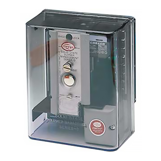
SOLID STATE
BURNER MANAGEMENT
CONTROLS
SERIES D30
®
APPROVED
DESCRIPTION
Fireye Series D30 Burner Management Controls provide ignition and main flame failure protection
for automatically ignited oil, gas and combination fuel burners. In conjunction with limit-operating
controls and interlock devices it automatically programs, with solid state timing logic, the burner/
blower motor, ignition, and main fuel valve(s). The control cycles automatically when the operating
control closes and following a power interruption, but must be manually reset following a safety
shutdown.
The start-up programming includes a safe start check on each start. If flame signal (real or simulated)
is detected, the ignition will not be energized and safety lockout will occur. Terminals are provided
for a main fuel valve proof of closure interlock, which must be closed before start-up and during
prepurge. Proof of the low fire start position is required before ignition. An interlock circuit is pro-
vided for air flow switches, fuel pressure switches etc. which must be closed during the prepurge and
firing period. The control system de-energizes all fuel valves within four seconds following flame
failure. An alarm circuit actuates audible and visual alarms following a safety lockout.
Plug-in amplifier modules permit the selection of Ultraviolet, repetitive self-check Ultraviolet,
AUTOCHECK infrared, or Rectification methods of flame detection. For increased safety and reli-
ability, Fireye 72D1R1-3 AUTOCHECK infrared amplifiers (using the pulsing flame signal) and
72DUVS-45UV5 Ultraviolet amplifier-scanner (using a scanner shutter) check the function of the
flame detecting system for any component failure during each burner firing cycle. Meter test jacks
on each amplifier module provide flame signal readout with a DC voltmeter.
The solid state programmer is a plug-in module. A test switch permits the operator to stop the pro-
gramming before energizing the main fuel valves, for test purposes.
The complete control incorporates plug-in design for easy installation. All flame scanners are minia-
turized. Fireye D30 Series controls directly replace similar Fireye C-Series models.
1
Advertisement
Table of Contents

Subscribe to Our Youtube Channel
Related Manuals for Fireye D30 Series


Summary of Contents for Fireye D30 Series
- Page 1 APPROVED DESCRIPTION Fireye Series D30 Burner Management Controls provide ignition and main flame failure protection for automatically ignited oil, gas and combination fuel burners. In conjunction with limit-operating controls and interlock devices it automatically programs, with solid state timing logic, the burner/ blower motor, ignition, and main fuel valve(s).
-
Page 2: Specifications
Canadian Standards Association: Certified: LR7989 Factory Mutual System: Approved: Report (J.I.) 1C1A1.AF Three LED lights on the Fireye chassis provide the following indication: • Air Flow — lights when interlock circuit is closed. • TFI — lights during pilot trial-for-ignition period. - Page 3 Check-Run Test Switch Plug-in Flame Amplifier Cover Retainer Lock-out Switch LED Indicators Plug-in Programmer Test Jack Red (+) DESCRIPTION OF FIREYE D-30 SYSTEM COMPONENTS Control Part Numbers Control Chassis and Cover 70D30 Plug-in Program Module 71D81-15 Second purge 71D80-30 Second purge...
-
Page 4: Ordering Information
REMOVING OLD CLIP REPLACING NEW CLIP Note: When a Fireye C-Series unit is replaced with a D-Series unit, the chassis retaining clip (for quarter turn fastener) in the wiring base must be replaced with a threaded clip that is supplied with each D-Series control. -
Page 5: Electrical Ratings
15 seconds. The use of control switches, solenoids, relays, etc. which chatter will lead to premature failure of switches in the Fireye control. Similarly, the contacts cannot be expected to handle short circuit currents without damage. It is important to run through a test operation (with fuel shut off) following the tripping of a circuit breaker, a blown fuse or any known instance of chattering. -
Page 6: Installing The Control
Reconnect the neutral wire (L2) at the power source. Remove the test probe from the grounded terminal and reconnect it to terminal L2 in the wiring base. With the other probe, touch each ter- minal. It is normal to obtain a resistance reading on the meter at some terminals during this test as there are resistive loads (coils-transformers-lamps, etc.) connected whose normal DC resis- tance may be less than 5 ohms. -
Page 7: Installation - Uv Scanners
Select a scanner location that will remain within the ambient temperature limits of the UV scan- ner. If cooling is required, use an insulating coupling (Fireye P/N 35-69 for UV1, UV2, UV8A scanners, P/N 35-127-1 for 45UV5) to reduce conducted heat. - Page 8 TYPICAL SCANNER INSTALLATIONS SCANNER DO NOT EXTEND FORCED MORE THAN CLEAN AIR HALF-WAY INTO (FROM DISCHARGE REFRACTORY OF FAN) DO NOT EXTEND MORE THAN HALF-WAY INTO REFRACTORY The maximum UV signal from a flame is found in the first one-third of the vis- INSULATING ible flame taken from the point where TUBING...
-
Page 9: Installation - Infrared Scanner Type 48Pt2
Selection of Wire. — Use #14, 16 or 18 wires with 75 C, 600 volt insulation for up to 100 foot distances (signal loss approximately 20% at 100 feet). — For extended scanner wiring up to 500 feet, and for shorter lengths to reduce signal loss, use a shielded wire (Belden 8254-RG-62/U coaxial cable, or equivalent) for each scanner wire of UV1, UV2 and UV8A and red wires of 45UV5-1009. -
Page 10: Installation - 69Nd1 Flame Rod
Force air into sighting tube. Make sure sighting tube does not extend more than halfway into refractory wall. Use Fireye sealing union (part #60-801) when using method 3 above. INSTALLATION — 69ND1 FLAME ROD The 69ND1 flame rod proves a gas pilot flame and/or main gas flame. It is a “spark plug” type unit consisting of 1/2"... -
Page 11: Description Of Operation
DESCRIPTION OF OPERATION Fireye control D30 with programmer 71D81 (15 second purge), 71D80 (30 second purge), 71D90 (90 second purge) and with amplifier 72D1R1 (Infrared), 72DUV1 (UV), 72DUVS4 and 72DUVSIT (UV-Self-checking), 72DRT1 (Rectification), provides the following burner operation. Note: For direct spark ignited oil burners, substitute the words “main oil valve” for “pilot valve.”... - Page 12 BURNER/BLOWER MOTOR (M) SPARK IGNITION BURNER PILOT VALVE INTERRUPTED (5) PILOT VALVE INTERMITTENT (6) MAIN FUEL VALVE (7) AIR FLOW INDICATORS FIREYE CONTROL TYPE 70D30 WITH PROGRAMMER 71D81 - 15 SECOND PURGE 71D80 - 30 SECOND PURGE 71D90 - 90 SECOND PURGE...
-
Page 13: Installation Testing
18-25 volts DC. Note: The Fireye 45UV5-1009 is a repetitive self-check scanner that contains a highly reliable shut- ter that closes every 4 seconds to initiate a system check. When the shutter closes, the test jack volt- age should go down to approximately zero, and then back to the normal reading in about 2 seconds. - Page 14 Flame Ignition And Fuel Valve Control Circuit Not Used Not Used Flame Amplifier Control Circuit Rod* FIREYE WIRING BASE TERMINALS NOT USED IMPORTANT; A Good Note: When A Flame Rod Is Earth Ground is Used, Jumper S2 To The Ter-...
- Page 15 Place the check-run switch in the check position. Turn power on and initiate a normal start-up. Reduce the fuel supply to the pilot until the “Fireye” light goes out. (If a test meter is used, the DC test jack voltage will be below 5 volts).
- Page 16 Operational Test When the installation and all burner adjustments are completed, the entire burner control system should be tested in accordance with the burner manufacturer’s instructions. The procedure should verify the correct operation of: Each operating control (temperature, pressure, etc.). Each limit switch (temperature, pressure, low water cutoff, etc.).
-
Page 17: Troubleshooting
Run-check switch during the pilot trial-for-ignition period of pilot ignited burners. Servicing Fireye D-Series units is facilitated by the use of plug-in programmer and amplifier modules. Trouble with installations equipped with Fireye D30 controls can be readily isolated by following the procedure in the sequence listed below. - Page 18 — Replace 72D series amplifier module. — Replace 70D30 control. Pilot not energized at the end of purge. Air Flow indicator on, TFI and FIREYE indicators off. — Low fire start switch open (or jumper wire not installed at terminals M-D).
- Page 19 — Pilot valve stuck open. — Wiring error. — Replace 70D30 control. Flame signal drops off while main burner fires. Air Flow indicator on Fireye indicator goes off. — Main burner improperly adjusted. — Flame scanner loses sight of flame.
-
Page 20: Maintenance
Amplifier will forewarn of any deterioration in the capability of the flame detector or its application. Contacts. There are no accessible contacts in the Fireye D30 Series control. Where contacts are used, their design assures long trouble-free life when the load circuits are maintained within the pub- lished load ratings. - Page 21 Operational test facilities shall be provided for measuring flame signal strength and line and load voltages. The control shall be a plug-in design. Plug-in solid state flame amplifiers shall be provided for the rectification, Infrared (AUTOCHECK), Ultraviolet or ultraviolet repetitive self-check flame detection. The burner management controls shall be Fireye series D-30.
- Page 22 5 11/16 WIRING BASE CONTROL WITH COVER (144.5) MOUNTING HOLES 2 7/16 AND WIRING BASE (61.9) KNOCKOUTS FOR 1/2” CONDUIT (7) 5 1/4 (133) 7 9/32 (185) 5 3/4 (146) 13/64 (177.8) (5.1) 1 3/4 (44.4) 25/32 (19.8) 11/16 KNOCKOUTS FOR (17.4) 1 3/16 (6.35)
- Page 24 Fireye warranty, as stated in its General Terms and Conditions of Sale, pertains only to the Fireye products and not to any other equipment or to the combined system or its overall performance.
Need help?
Do you have a question about the D30 Series and is the answer not in the manual?
Questions and answers