Table of Contents
Advertisement
Quick Links
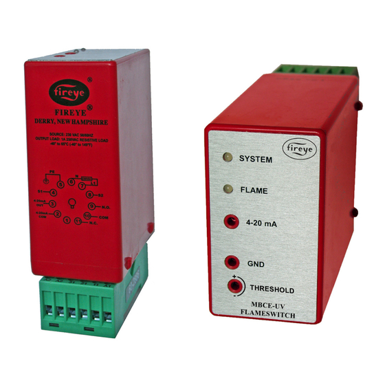
DESCRIPTION
The MBCE-110/230UV modules provide visual indication and electrical outputs that
signal the user regarding flame presence in a combustion chamber. The module uses
Fireye UV scanners to sense flame presence independently or as components in a
burner management system. Many operational characteristics are provided including:
CE certified
•
Self-contained: 110 VAC, 50/60 Hz: MBCE-110UV-1, MBCE-110UV-2
•
UV scanner compatible*
•
Flame ON/OFF LED indicator
•
4-20mA output permits direct reading of flame signal strength
•
Uses CE certified 11-pin relay base
•
Panel surface or DIN-rail mounting
•
Flame pull-in threshold adjustment
•
The module provides a cost effective method of monitoring flames using UV sensing.
The MBCE-UV is intended for non-permanent operation (burner must be recycled at
least once every 24 hours). The MBCE-UV is ideally suited for flame detection in nat-
ural gas applications; however, it can be used for flame detection in propane and light
fuel oil applications.
Check with Fireye for more details by contacting your local distributor or by check-
ing the Fireye home page at: www.fireye.com.
NOTE: When the MBCE-110/230UV modules are used, additional means must be furnished to provide
those functions usually provided by flame safeguard control systems to meet local regulations (i.e.:
safe start check, valve closure, starting and running interlocks, safety timings, etc.).
The MBCE-UV shall be powered continuously from a separate source other than the Burner control
per EN 298. * see ordering information
NOTICE: When Fireye products are combined with equipment manufactured by others and/
or integrated into systems designed or manufactured by others, the Fireye warranty, as stated
in its General Terms and Conditions of Sale, pertains only to the Fireye products and not to any
other equipment or to the combined system or its overall performance.
MBCE-110UV-3, MBCE-110UV-4
230 VAC, 50/60 Hz: MBCE-230UV-1, MBCE-230UV-3
MBCE-110/230UV
Flame Sensor
Module
MBCE-1002
FEBRUARY 3, 2017
1
Advertisement
Table of Contents

Subscribe to Our Youtube Channel
Related Manuals for Fireye MBCE-110UV Series


Summary of Contents for Fireye MBCE-110UV Series
- Page 1 Fireye warranty, as stated in its General Terms and Conditions of Sale, pertains only to the Fireye products and not to any other equipment or to the combined system or its overall performance.
-
Page 2: Ordering Information
NOTICE: MBCE-UV module does not have any user serviceable parts. If the unit has a problem, return the unit to your local distributor, or contact Fireye directly. Adequate disconnect means and overload protection is required. A 1 amp external fuse is... - Page 3 FIGURE 1. DIMENSIONS OF DIN RAILS, WIRING BASES AND FLAME SWITCH MODULES SHOWN IN INCHES (MM) (50.8mm) (76.2mm) 1.49 37.82 3.18 DIA. TYP. 1.03 26.09 2.96 75.06 (101.6mm) .14 3.56 1.46 37.08 STYLE: 11 pin octal, snap-mount/surface mount TYPE OF CONNECTION: Screw connection STRIPPING LENGTH: 10mm SCREW THREAD: M3 WIRE SIZE: Maximum up to 2 - #14AWG each terminal...
-
Page 4: Flame Scanners
Position the UV1AL, UV5, or UV90L scanner within 30 inches of the flame to be monitored. Select a scanner location that remains within the ambient temperature limits of the UV Scanner. If cooling is required, use an insulating coupling (Fireye #35-69 for UV1AL to reduce con- ducted heat). -
Page 5: Wiring - Uv Scanners
FIGURE 2. TYPICAL SCANNER INSTALLATIONS SCANNER DO NOT EXTEND FORCED MORE THAN CLEAN AIR HALF-WAY INTO (FROM DISCHARGE OF FAN) REFRACTORY DO NOT EXTEND MORE THAN HALF-WAY INTO REFRACTORY The maximum UV signal INSULATING TUBING from a flame is found in the SEALING first one-third of the visible FORCED... -
Page 6: Threshold Adjustment
Route scanner wiring a sufficient distance from ignition and other high voltage or high current wiring to avoid electrical interference. Interference from ground currents, nearby conductors, radio-frequency emitters (wireless devices), and inverter drives can induce false flame signals. In some applications shielded cables can help reduce interference with the shield connected to ground at the control end only. -
Page 7: Indication Leds
INDICATION LEDS The MBCE-UV Flameswitch contains two bi-color LEDs. These are used to provide flame status and alarm conditions. See the following table. View the LEDs through the cutout located on the top side of the unit. Table 1: COLOR DEVICE STATUS GREEN... - Page 8 WIRING BASE PINOUT INFORMATION The following table shows the wiring information and the ratings. To guarantee proper operation, the MBCE-UV module MUST NOT be operated above its maximum rating. TERMINAL NO. TERMINAL NAME DESCRIPTION DIRECTION RATING (11) OPEN UNUSED (A1) 4-20mA COM 4-20mA COMMON...
- Page 9 FIGURE 3. TYPICAL APPLICATION - MBCE-110/230UV CAUTION: SPECIAL CONDITIONS OF USE The equipment, wiring base, and its enclosure are considered hazardous live parts and shall be installed in compliance with the enclosure, mounting spacing and segregation requirements of the ultimate application to protect the user against electric shock and the equipment against ingress of water and dust.
- Page 10 Fireye shall be limited exclusively to the right to replacement or repair as above provided. In no event shall Fireye be liable for consequential or special damages of any nature that may arise in connection with such product or part.
Need help?
Do you have a question about the MBCE-110UV Series and is the answer not in the manual?
Questions and answers