Advertisement
Quick Links
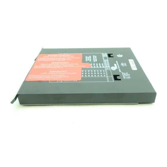
The Fireye EP160, EP161 (extended MTFI), EP163 (programmable), EP170 and EP174 (early spark
termination), EP165, EP166 (pilot stabilization) or EP177 (early spark termination and programma-
ble operating parameters) programmer modules are used with the FLAME-MONITOR Burner Man-
agement Control System (P/N's E100 and E110). Several operational characteristics of the
programmer are determined by six (6) dipswitches located on the side of the programmer. These
characteristics include forced blower motor start delay (dipswitch 1), extended purge timing
(dipswitches 3, 4, 5) and the option requiring the 3-P running interlock circuit to be proven open at
the start of the operating cycle (dipswitch 6). Dipswitch 2 is inactive. Models EP163 and EP177
characteristics are programmed via the ED510 Display Module, rather than by dipswitch.
The EP160, EP161, EP163, EP165, EP166, EP170, EP174 and EP177 programmers provide start-up
programming, safe-start check, and flame monitoring supervision. They insure open damper (high
purge) prepurge, proof of low fire position, and fuel valve end switch safety checks. A running inter-
lock circuit on the FLAME-MONITOR system constantly monitors the limit switches, air flow
switches, and fuel pressure switches through the programmer. The programmer control is designed
to initiate a safety lockout if any of these circuits are open at the improper point in the control cycle.
The programmer module will de-energize all fuel valve circuits within four (4) seconds (max.) fol-
lowing a flame failure [two (2) seconds for the EP165 and EP166], or at the end of the pilot trial for
ignition period if no flame is detected. An alarm circuit will be energized following a safety lockout.
The programmer module includes an RJ45 style connector to interface with an integral or remote
alpha-numeric display (P/N ED510). It is also backward compatible with the ED500 display. It
includes two (2) additional RJ style connectors to connect to an E500 communication interface in a
multi-drop configuration or allow communication via a Modbus protocol. The programmer will also
communicate with the E500 via the ED550 cables to provide backward compatibility.
The programmer is the heart of the FLAME-MONITOR System and features a plug-in design for
ease of installation. It is micro-processor based and stores the burner cycles, burner hours, system
hours, and lockout history (with burner cycle and burner hour time stamp) which are accessible via
the ED510 alpha-numeric display, E500 Communication Interface, InTouch Wireless Monitoring
System or Modbus communications. If replaced, the new programmer card will begin accumulating
a new history.
Refer to Bulletin E-1101 for detailed information on the FLAME-MONITOR System.
Advertisement

Related Manuals for Fireye EP160


Summary of Contents for Fireye EP160
- Page 1 The Fireye EP160, EP161 (extended MTFI), EP163 (programmable), EP170 and EP174 (early spark termination), EP165, EP166 (pilot stabilization) or EP177 (early spark termination and programma- ble operating parameters) programmer modules are used with the FLAME-MONITOR Burner Man- agement Control System (P/N’s E100 and E110). Several operational characteristics of the programmer are determined by six (6) dipswitches located on the side of the programmer.
- Page 2 Remove control from the wiring base before proceeding. The EP programmer modules are used with the Fireye EB700 and E110 chassis. They are installed in the chassis by inserting the EP programmer module into the second slot on the control. This slot is marked “Programmer Module”...
- Page 3 Note: EP160, EP161, EP163, EP165, EP166, EP170, EP174 and EP177 have non-recycle running interlock circuits (3/P). WARNING: While all controls are mechanically interchangeable because they mate with a com- mon wiring base, you must select the correct model for your application. Inappropriate application of a control could result in an unsafe condition hazardous to life and property.
- Page 6 Dipswitches 3, 4, & 5 determine the purge timing for the programmer module. Purge timings are selectable from 30 seconds to 30 minutes. On the EP160, EP161, EP165, EP166, EP170 program- mer, the purge timing is not initiated until the firing rate motor is driven to the high fire position (10- X made) and the high fire switch is proven closed (term D-8).
- Page 7 (such as an installation where there is no High-Fire -Purge switch installed, and a perma- nent jumper is wired between terminals D-8), dipswitch 6 should not be enabled. The EP160, EP161, EP165, EP166, EP170 programmers are shipped with this option disabled (switch 6 is down).
- Page 8 Two display modules are available for the FLAME-MONITOR control system (P/N's ED500 and ED510). The ED500 is an 8 character LED display that physically mounts in the card rack of the EB700 chassis. The ED510 is a 2 line by 16 character LCD with keypad to provide both current and historical information pertaining to the operation of the control.
- Page 9 The EP Programmer modules have a set of six (6) dipswitches on the side of the programmer to modify various functions associated with the operation of the programmer (e.g. purge timing, prove 3-P circuit open to start, etc.). THESE FUNCTIONS BECOME PERMANENT AFTER THE CONTROL HAS BEEN POWERED FOR EIGHT (8) HOURS.
-
Page 10: Post Purge
Press the SCRL key to advance through the allowable selections. The selections will roll over from the last selection to the first one. Press and hold the RESET button for one second to choose and store in memory the appropriate selection. -
Page 11: Purge Time
The EP177 Programmer Module provides early spark termination for the spark ignition that is con- nected to terminal 5. The EP177 also waits indefinitely for the M-D low fire start switch to close. This programmer model also provides a number of operational characteristics that are selected via the ED510 Keypad/Display rather than by dipswitch selection. - Page 12 The pilot valve terminal can be set for interrupted or intermittent operation. If intermittent (INTMT), terminal 6 will remain energized during the firing cycle. PROVE D-8 OPEN default is N The open damper proving switch must not be closed at the start of a burner cycle. PROVE M-D OPEN default is N The closed or low fire start position of the damper must not be closed at the end of open damper pre-...
- Page 13 Programmer modules (with Engineering code 28 or later) include an RJ45 style connector to connect to an alpha-numeric display (P/N ED510). The ED510 can snap onto the front cover of the program- mer module or be mounted remotely (See Bulletin E-8101— Remote mounting kit). The ED580 cable (provided with ED510 Display) then plugs into the RJ45 style connectors on both the ED510 display and programmer module.
- Page 14 E500 via the RS485 interface: Press the SCRL key until the screen displays PROGRAM SETUP Press the MODE key and the screen displays PROGRAMMER EP160 (or appropriate model). Press the SCRL key until the screen displays UNIT ADDRESS #00 (or appropriate address).
- Page 15 It is suggested that polling intervals not be less than 200 mSec per request. Requesting data such as burner minutes, system minutes and burner cycles should be kept at a minimum due to the amount of processing time required to gather that data. Messages 00, 05, 08, 10, 15, 21 and 26 are unique in that a limited number of successive registers can be combined with these requests.
- Page 16 1 in any bit position in the OUTPUT register signifies the relay as being energized. A ‘1’ in the opto-coupler position indicates the opto-coupler is on or interlock closed. Refer to Fireye bulletin E-1101 for terminal designations.
- Page 17 LOGSTAT is an indication of what logic module the control is currently operating in during its cycle and is used for diagnostic purposes only. If a lockout occurs the current value of LOGSTAT is stored as part of the lockout information. The message displayed corresponds to the current logic module. Logstat represents the current software module the Flame-Monitor is currently executing.
- Page 19 LCD display with keypad for local access to historical information) or ED500 (8 character LED display). For purposes of illustration for this bulletin, we will be looking at the EP160 Pro- grammer functions and messages associated with the ED510 display module. The ED500 display messages will be abbreviated versions of those of the ED510.
- Page 20 When the firing rate motor reaches its open damper position, the Hi Purge switch closes (D-8) and the prepurge interval of 30 seconds is initiated. The ED510 will display: If the D-8 circuit does not close, the program will hold in this position for ten minutes waiting for it to close.
- Page 21 With current ED510’s (Engineering code 3 or higher), the LED display backlight remains ON at all times. With earlier ED510 versions, the backlight will be lit when the L1-13 (operating control) cir- cuit is closed, and OFF when the L1-13 circuit is open. With the earlier displays, depressing any key will light the display for three (3) minutes.
- Page 22 Lockout and burner history can be displayed by using the ED510 keypad and display. Refer to Bulle- tins ED-5101 or E-1101. The function of the low fire start and interlock circuit internally in a Fireye Flame-Monitor unit is accomplished by highly reliable solid state electronic circuitry. This prohibits the connection of power consuming devices (i.e.
- Page 24 Fireye warranty, as stated in its General Terms and Conditions of Sale, pertains only to the Fireye products and not to any other equipment or to the combined system or its overall performance.
Need help?
Do you have a question about the EP160 and is the answer not in the manual?
Questions and answers