Table of Contents
Advertisement
Quick Links
DESCRIPTION
The Fireye BurnerLogix
designed to provide the proper burner sequencing, ignition, and flame monitoring protection on
automatically ignited oil, gas, and combination fuel burners. In conjunction with limit and
operating controls, it programs the burner/blower motor, ignition, and fuel valves to provide for
proper and safe burner operation. Through SMART LED'S, the control provides current operating
status and lockout information in the event of a safety shutdown. Optional OLED and LCD
displays are available that may be either plugged in or mounted remotely to give full language
descriptors of current status and diagnostic lockout information. Refer to BurnerLogix
PROGRAMMER SELECTION later in this document for the various combinations of
programmer and display modules.
A complete BurnerLogix system includes the YB110 (YB230) chassis equipped with the type
of flame amplifier required for the application, appropriate flame detector, plug-in programmer
module, wiring base and optional alpha-numeric display. Interchangeable programmer modules
allow for complete versatility in selection of function, timing, and flame failure response times.
The optional alpha-numeric display has 2 lines by 16 characters per line. It is available in either
vacuum fluorescent or liquid crystal formats. The advantage of OLED is high brightness and
extended temperature range down to –40°F. Both displays contain a fully functional keypad.
You can easily scroll through the various menus to view the current operating status, review
programmer configuration, and lockout history. When mounted remotely, the displays provide
NEMA 4x(IP66) protection. An advantage of the BurnerLogix control family is the ability to set
many of the operating parameters associated with proper and reliable burner operation allowing
inventory of various programmer types to be kept to a minimum.
The YB110 (YB230) is a chassis/flame amplifier module complete with mounting screws and
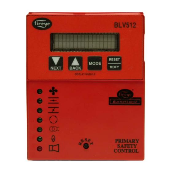
blank display module. The display module BLV512 (OLED) or BLL510 (LCD), if required,
must be ordered separately. Interchangeable YP programmer modules allow for complete
versatility in selection of control function, timing, and flame scanning means. Functions such as
pre-purge time, recycling or non-recycling interlocks, high fire proving interlock, and trial for
ignition timing of the pilot and main flame are determined by the programmer module. The
BurnerLogix system can be used with ultra-violet, auto-check infrared, flame rod,
self-check ultra-violet flame scanners or direct coupled integrated scanners by choosing the
proper chassis/flame amplifier module.
© 2023 Carrier
GEN II
GEN II
Integrated Burner Management Control
TM
System is a microprocessor-based burner management control system
YB110/YB230 FIREYE
BurnerLogiX
Microprocessor-Based
BL-1001
September 19, 2023
TM
1
Advertisement
Table of Contents

Related Manuals for Fireye BurnerLogiX YB110


Summary of Contents for Fireye BurnerLogiX YB110
-
Page 1: Description
GEN II Integrated Burner Management Control DESCRIPTION The Fireye BurnerLogix System is a microprocessor-based burner management control system designed to provide the proper burner sequencing, ignition, and flame monitoring protection on automatically ignited oil, gas, and combination fuel burners. In conjunction with limit and operating controls, it programs the burner/blower motor, ignition, and fuel valves to provide for proper and safe burner operation. - Page 2 Wiring bases for the BurnerLogix control are available for easy installation or with an integral terminal block capable of a accepting up to 2 X 14 AWG wires. The wiring base terminal block is available with knockouts for conduit or open ended for cabinet mounting. Additional functions of the BurnerLogix system include: •...
-
Page 3: Table Of Contents
Table of Contents DESCRIPTION ................................ 1 BURNERLOGIX SPECIFICATIONS ........................6 PART NUMBERS AND APPROVALS ........................9 ORDERING INFORMATION ..........................10 INSTALLATION PROCEDURE ..........................13 WIRING BASE ..............................14 PTFI*MTFI TIMINGS ............................18 LED INDICATOR LIGHTS ..........................20 REPLACEABLE FUSE ............................21 OPERATING CONTROL FUNCTIONS........................ - Page 4 4-20 mA TEST JACKS ............................66 CHECK RUN SWITCH ............................67 VALVE PROVING .............................. 68 OPERATIONAL TEST ............................72 TEST CHECKOUT PROCEDURES ........................72 BURNERLOGIX GROUNDING RULES ......................74 MAINTENANCE ..............................75 NOTICE ................................. 78 WARRANTIES ............................... 78 © 2023 Carrier...
- Page 5 Table of Figures FIGURE 1. BURNERLOGIX ORDERING INFORMATION ............13 FIGURE 2.
-
Page 6: Burnerlogix Specifications
BURNERLOGIX SPECIFICATIONS Supply Voltage: YB110 120 VAC (+10%, -15%) 50/60 Hz YB230 230 VAC (+10%, -15%) 50/60 Hz Power Consumption: 25 VA Temperature Rating: -40°C (-40°F) to +60°C (140°F) Protection Category: YB110 (YB230) control NEMA 1 (IP01) Display, remote mounted NEMA 4X (IP66) Unit Dimensions: Wiring base 60-2812-1, 60-2814-1 - 4.0"... -
Page 7: Table 2: Load Ratings
Table 2: LOAD RATINGS Terminal Typical Load A. Maximum Rating B. Maximum Rating C. Alternate Rating @120V-50/60 Hz @230V-50/60 Hz Burner/Blower Motor 9.8 F.L.A. * 4.0 F.L.A. * 240 VA Pilot Duty 58 L.R.A. 20 L.R.A. (Motor Starter Coil) 10-11-12-X Modulator 125 VA Pilot Duty Alarm... - Page 8 CAUTION: Published load ratings assume that no contact will be required to handle inrush current more often than once in 15 seconds. Using control switches, solenoid, relays, etc. which chatter lead to premature failure. Run through a test operation (with fuel shut off) following the tripping of a circuit breaker, a blown fuse, or any known instance of chattering of any external current consuming devices.
-
Page 9: Part Numbers And Approvals
PART NUMBERS AND APPROVALS Table 3: AGENCY APPROVALS BurnerLogix APPROVED Chassis/Flame Amp. Module YB110UV YB110UVSC YB110IR YB110IR2 YB110FR YB110DC YB230UV YB230UVSC YB230IR YB230IR2 YB230FR YB230DC BurnerLogix Programmer Module YP100 YP102 YP138 YP118 YP183 YP200 YP202 YP300 YP302 YP113 YP115 YP148 YP184 BurnerLogix Displays BLV512... -
Page 10: Ordering Information
Table 4: APPLICABLE BULLETINS Programmers, Non-recycle Operation Programmers, Recycle Operation YP-1001 Programmers, Non-modulating Displays BD-5001 Wiring base installation, 60-2812-1 133-677 Wiring base installation, 60-2814-1 133-677 ORDERING INFORMATION Table 5: BurnerLogix Chassis/Flame Amplifier Module YB110UV 120 VAC input with UV non-self-check amplifier 120 VAC input with UV self-check amplifier YB110UVSC 120 VAC input with IR auto-check amplifier... -
Page 11: Table 7: Burnerlogix Displays
Alarm annunciation system using wireless technology IT1000 Parallel Positioning System PPC6000 Shutter drive assembly for redundant self-check scanners 61-5745-3 Table 10: SCANNER SELECTION FIREYE P/N DESCRIPTION USE WITH CHASSIS BULLETIN 48PT2-1003 Infrared 1/2" straight mount 96"(2438mm) TC-ER cable YB110IR 48PT2-9003 Infrared 1/2"... - Page 12 Self-check UV 1" BSP, 102-264VAC, Suitable for hazardous locations. Self- YB110UVSC 55UV5-1009 YB230UVSC check UV 1" NPT, 102-264VAC, Suitable for hazardous locations. PHOENIX USE WITH FIREYE P/N DESCRIPTION BULLETIN CHASSIS 85UVF4-1QDWR Phoenix Integrated Scanner, 4 sec FFRT – Ultra-violet with 8-pin electrical quick disconnect. FM, UL_CUS approved.
-
Page 13: Figure 1. Burnerlogix Ordering Information
Figure 1. BURNERLOGIX ORDERING INFORMATION CHASSIS/AMPLIFIER 120 VAC, 50/60 Hz GEN II GEN II YB110UV YB110UVSC YB110IR YB110FR FRONT VIEW YB110DC (WITH OPTIONAL DISPLAY INSTALLED) 230 VAC, 50/60 Hz GEN II GEN II YB230UV YB230 UVSC YB230IR YB23FR YB230DC FRONT VIEW SIDE VIEW (WITH OPTIONAL DISPLAY INSTALLED) (WITH OPTIONAL PROGRAMMER AND DISPLAY INSTALLED) -
Page 14: Installation Procedure
INSTALLATION PROCEDURE WIRING BASE Select either the terminal block style (60-2812-1, 60-2814-1). Either wiring base type can be mounted on a din rail or directly mounted to the cabinet back plate. Refer to Figure 2 for mounting dimensions. Figure 2. WIRING BASE DETAILS HEIGHT WITH CONTROL INSTALLED IS 5.8"... - Page 15 INSTALLATION PROCEDURE WIRING BASE Install the wiring base where the relative humidity never reaches the saturation point. The Burner-Logix system is designed to operate in a maximum 90% relative humidity continuous, non-condensing environment. Do not install the BurnerLogix system where it can be subjected to vibration in excess of 0.5G continuous maximum vibration.
- Page 16 INSTALLING THE YP PROGRAMMER MODULE Figure 3. YP110 PROGRAMMER The YP programmer module plugs into the side of the YB110 (YB230) chassis module. They can only be installed in one direction. DO NOT ATTEMPT FORCE PROGRAMMER INTO CHASSIS. Referring to the illustration on the right, align the holes in the YP programmer housing with the posts located within the YB chassis.
-
Page 17: Table 12: Burnerlogix Programmer Selection
LEARN" OPERATION BE PERFORMED TO GUARANTEE RELIABLE OPERATION. REFER TO IR LEARN SECTION FOR MORE INFORMATION. Table 12: BURNERLOGIX PROGRAMMER SELECTION FIREYE Pre-purge Proven High Proven Low Pilot Terminal, Early Spark ValveProve ValveProve ValveProve FIREYE PART Termination NUMBER PART Programming Fire Interlock Fire Interlock Interrupted or Pre-Check Evacuation Pressurization NUMBER... -
Page 18: Ptfi*Mtfi Timings
Table 12 Continued FIREYE PTFI PTFI PTFI MTFI MTFI MTFI Flame Fail Firing Rate PILOT PROVING Running PART (5/6) (W/6) (W/5) 6 Only (5/6) (W/6) (W/5) Time (Seconds) Motor Interlock NUMBER (3-P) SETTINGS SHOWN ARE FACTORY DEFAULT YP100 1 10/10... -
Page 19: Table 13: Ptfi & Mtfi Timing
The selections provided for PTFI*MTFI timings are: Table 13: PILOT AND MAIN TRIAL FOR IGNITION TIMING PTFI MTFI SELECTION COMMENT Term 5 Term 6 Term 5 Term 6 (Term W for YP148/YP184 (Term 5 for YP148/YP184 (Term W for YP148/YP184 (Term 5 for YP148/YP184 Programmer) Programmer) -
Page 20: Led Indicator Lights
LED INDICATOR LIGHTS The BurnerLogix YB control module has seven (7) LED indicator lights. These annunciate the operating status of the control and provide the reason for the last lockout condition. The “Open Damper” and “Close Damper” LED's provide easy set-up of the modulating motor end switches. -
Page 21: Replaceable Fuse
Using an appropriate tool, remove the defective fuse and discard. Install a Fireye replacement fuse (P/N 23-197). Re-install the BurnerLogix control in accordance with the installation procedure detailed in a previous section. -
Page 22: Operating Control Functions
OPERATING CONTROL FUNCTIONS Operating Controls: Pressure or temperature activated, the operating control closes, causing the burner start-up sequence to begin. When the operating control opens, the burner shuts off. The operating control is connected in the L1-3 circuit on the wiring base. -
Page 23: Keypad Description
Figure 4. KEYPAD DESCRIPTION STANDBY PROGRAM SETUP > The NEXT key is used to scroll down through the various menus. It is used to increment in the modify mode. The BACK key is used to scroll up through the menus. It is also used to decrement the value when in the modify mode. -
Page 24: Program Set Up Sub-Menu
PROGRAM SET UP SUB-MENU The sub-menu "PROGRAM SETUP" allows the user to review the various operational settings of the programmer module (e.g., programmer type, purge timing, etc.) and in some instances modify the operational parameters to suit the application requirement. Use the MODE key to enter and exit the sub-menu. -
Page 25: Table 15: Modifiable Parameters Located In Program Setup Menu
Table 15: MODIFIABLE PARAMETERS LOCATED IN PROGRAM SETUP MENU Parameter Factory Default Range Description 0:00s – 60:00m, 1 second increments. Applies to open damper purge time in YP1XX and YP2XX programmers and low fire Purge time 00:30s 0:00s-60:00m, YP113 start time in YP3XX programmers. 0:00s-60:00m, YP115 (0:00s - 60:00m in YP3XX) Note: 0 sec purge requires a display with Engr code 9 or higher and chassis Engr code of 11 or higher... -
Page 26: To View And Modify A Programmable Parameter
Note: 1. For YP100, YP102, YP112, YP113, YP115, YP118, YP120, YP183, YP200, YP300, YP302, YP138 programmers, Shaded parameters not affected by 8-hour burn-in or LOCK SETTINGS. 2. For YP148 and YP184 programmers, the 8-hour burn-in or LOCK SETTINGS feature is not applicable for any of the parameters. -
Page 27: Installation - Uv Scanners
45UV5 within 72 inches, closer if possible. Select a scanner location that remains within the ambient temperature limits of the UV Scanner. If cooling is required, use an insulating coupling (Fireye #35-69 for UV1A, UV2 Scanners, #35127-1 for 45UV5) to reduce conducted heat. -
Page 28: Operation - 45Uv5 & 55Uv5 Self-Checking Uv Scanner
Figure 9. TYPICAL SCANNER INSTALLATIONS OPERATION — 45UV5 & 55UV5 SELF-CHECKING UV SCANNER Self-checking ultra-violet scanners are used in applications where burner firing operation is continuous or where the burner is on for long periods of time without recycling and UV detection is the best alternative. In addition, ultra-violet self-checking systems are mandatory in some locations. -
Page 29: Wiring - Uv Scanners
WIRING - UV SCANNERS To connect the scanner to the control, the UV1A Scanner is supplied with either 36"(.9m) or 72" (1.8m) of flexible cable. The 45UV5 is supplied with four 72” (1.8m) lead wires. Install them in a suitable length of flexible armor cable and connect it to the control. -
Page 30: Operation - Ir Learn
WIRING Attach the cable supplied with the scanner to a junction box. Splice the cable wires to a pair of wires not smaller than #l8. Install the complete run in a separate conduit to the control. Continuous conduit bonding between scanner and the control is mandatory! Scanner may be located up to 100 feet from control. Do not pass scanner wiring through any junction box containing other wires. - Page 31 The LEARN process is not subject to the 8-hour burn-in and therefore will always be available. If the LEARN process is activated at STANDBY, the LEARN process will involve both pilot and main flame. If the LEARN process is activated during the main firing period (AUTO) the LEARN process will only involve the main flame learn. During this LEARN process in AUTO, the thresholds for pilot flame are not affected.
-
Page 32: Installation - 69Nd1 Flame Rod
Use 6" to 8" (152.4mm x 203.2mm) length of pipe between scanner and hot furnace front plate. Use an insulating tube (P/N 35-69) on the end of the iron pipe. Force air into the sighting tube. Use Fireye Sealing Union (P/N 60-801). Make sure your sighting tube does not extend more than halfway into refractory wall. -
Page 33: Installation - 85 Series Phoenix Scanner
INSTALLATION - 85 SERIES PHOENIX SCANNER Fireye Phoenix 85UVF self-checking scanners are used to detect 295 to 340 nanometers wavelength ultraviolet emissions. Fireye Phoenix 85IRF self-checking scanners are used to detect 830 to 1100 nanometers wavelength infrared emissions. Fireye Phoenix scanners are suited for application to duct burners, industrial gas/oil burners, refinery applications, ignition systems and Low NOx detection and for continuous or non-continuous burner operation. -
Page 34: Figure 13. Burnerlogix Tyb110Dc/Yb230Dc With 85Uvf4-1Qdwr Scanner
Notes: Flame relay contacts are shown in the de-energized (no flame condition). Fault relay contacts are shown in de-energized (fault) condition. BMS = Burner Management System (by others). Do not use Red as 24-volt ground. External 2.0 Amp fuses recommended. A safety ground screw is provided on the scanner end plate. -
Page 35: Installation - 95 Series Insight Scanners
Fireye Windows 95/98/NT user software. All FIREYE InSight scanner models are powered by 24 Vdc and contain electronic self-checking (no mechanical shutter required). The scanners contain an eight-character alpha-numeric LED display and a four (4) push-button keypad to enable the user to view operating parameters and select set-points. -
Page 36: Figure 14. Insight Wiring Diagram
Figure 14. INSIGHT WIRING DIAGRAM Notes: Flame relay contacts are shown in de-energized (no flame) condition. Fault relay contacts are shown in de-energized (fault) condition. Brown and orange wires are a twisted pair. Connect cable shield to earth ground at the power source. With Remote File Select programmed as “LINE”, external switches SW1/SW2 (not furnished) select between two (S1 Models) or four (S2 Models) internal memory files, when connected to 24Vdc (-) supply. -
Page 37: Figure 15. Connect Burnerlogix & Insight I
Figure 15. CONNECT BURNERLOGIX & INSIGHT I (WR= with resistor) CABLEGLAND FLEX CONDUIT CONNECTORS CONNECTORS © 2023 Carrier... -
Page 38: System Info Sub-Menu
YP style programmer is being used, it is necessary to check the bulletin covering the specific programmer for exact details. Refer to the suggestions shown in this bulletin before proceeding to power the Fireye YB110 (YB230) BurnerLogix system. Items such as scanner installation, short circuit tests and safety information must be carefully reviewed. -
Page 39: Yp100 Operating Sequence
YP100 OPERATING SEQUENCE Figure 17. © 2023 Carrier... -
Page 40: Start-Up (Normal Cycle)
START-UP (NORMAL CYCLE) Note: For direct spark ignited oil burners, substitute the words Main-Oil Valve for Pilot Valve. Constant 120 VAC must be available to the Ll-L2 terminals only on the wiring base. The operating control circuits (Ll-3) will close, signaling the burner to start its firing sequence. - Page 41 PTFI FLAME SIGNAL With flame proven at the end of PTFI, the main flame trial for ignition (MTFI) period begins. Terminal 7 is energized. The BLV512 displays: MTFI FLAME SIGNAL Terminal 5 is de-energized 10 seconds later and Terminal 6 is de-energized after another 5 seconds. 10.
-
Page 42: Yp200 Operating Sequence
YP200 OPERATING SEQUENCE Figure 18. © 2023 Carrier... -
Page 43: Yp300 Operating Sequence
YP300 OPERATING SEQUENCE Figure 19. Ignore M-8 Input © 2023 Carrier... -
Page 44: Figure 20. Yp148 Operating Sequence Disabled
Figure 20. YP148 OPERATING SEQUENCE WITH VALVE PROVING & LOW GAS PRESSURE CHECK DISABLED *For figure 20 & 21: LFS must be closed during PTFI ONLY if “prove M-D TFI” has been selected YES Figure21. YP148 OPERATING SEQUENCE WITH VALVE PROVING & LOW GAS PRESSURE CHECK ENABLED ©... -
Page 45: Figure 22 Burnerlogix Wiring Diagram
Figure 22. BURNERLOGIX WIRING DIAGRAM Purge air switch from M to 8 not required for YP200. YP200 programmers recycles on 3-P open and a minimum purge time of 30secs should be configured for these programmers to recycle. Terminal 6 selectable interrupted/intermittent pilot. Terminal W active first 5 seconds of PTFI (YP100 Series only). -
Page 46: Yp138 Programmer
Figure 23. YP300 WIRING DIAGRAM YP118, YP138 PROGRAMMER The YP118 and YP138 programmers offer burner operation similar to the YP100 programmer but with extended functions that might enhance burner operation such as increased turndown. The YP138 programmer makes use of additional inputs on terminals 16 and 21. Both terminals 16 (PILOT HOLD) and 21 (START INPUT) are line voltage input. - Page 47 Figure 24. YP138 WIRING DIAGRAM © 2023 Carrier...
- Page 48 Terminal 21 holds the system indefinitely at the end of low fire start. When opened (off) terminal 21 starts pilot trial for ignition. If the countdown method is set, at the end of a low fire start period the display indicates: HOLD 00:00 T21 INPUT...
-
Page 49: Yp148 Programmer
Once terminal 16 is de-energized, the system proceeds to the MTFI period with terminal 7 (main valve energized). If selected to be on, terminal 5 with the ignitor becomes energized during MTFI in accordance with the PTFI*MTFI TIMINGS selection. At the conclusion of the MTFI period and as selected by the PTFI*MTFI TIMINGS selection and terminal 6 as interrupted/intermittent, terminals 5 and 6 assume their respective states. - Page 50 Figure 25. YP148 WIRING DIAGRAM 1. SUGGESTED WIRING DIAGRAM FOR YP148/184 PROGRAMMER for VP@PRE-PURGE CONFIGURATION 2. SUGGESTED WIRING DIAGRAM FOR YP148/184 PROGRAMMER for VP@POST-PURGE CONFIGURATION Terminal 5 selectable interrupted/intermittent pilot. See chart on Table 2 for selectable timings. © 2023 Carrier...
- Page 51 2. Fuel Selection (Terminal 16) is active HIGH for GAS fuel and active LOW for OIL fuel. 3. Fireye recommends that valve proving be performed during pre-purge to capture possible off cycle leaks before attempting ignition. In addition, the post purge wiring may trigger inaccurate alarms such as a 3 – P lockout if the recycle LWCO opens during run.
- Page 52 Notes on operation: Terminal 16 is used for selection of fuel type between OIL or GAS, providing full burner operation even if two fuels are fired simultaneously. Fuel selection (terminal 16) is active HIGH for GAS fuel type and active LOW for OIL fuel type. The fuel selection between OIL or GAS shall be made only before the start of burner cycle i.e., in STANDBY state only.
-
Page 53: Lockouts
LOCKOUTS When a safety shutdown occurs, the control indicates through the LED’s the reason for the lockout. If equipped, it displays a lockout message and when in the cycle the lockout occurred. The alarm circuit (Terminal “A”) is energized. The non-volatile memory remembers the status of the control even if a power failure occurs. By momentarily depressing and releasing the reset button on the control or the display keypad, the control can be reset. -
Page 54: Diagnostic Messages
If flame is detected when the operating control (L1-3) is open, the control waits sixty (60) seconds and then locks out if flame is still present. If the operating control closes and flame is detected during purge, the control drops back to the Standby position and de-energizes the blower motor (Term M). If the flame signal goes away within sixty (60) seconds, the control proceeds with a normal start-up. - Page 55 Notes: Manual Reset is required following any non-volatile lockout. Depressing and releasing the reset button during a cycle causes the Burnerlogix control to shut the burner down and recycle. The YP113 and YP115 programmers limit the amount of reset attempts to 5 tries. This internal counter gets reset to 0 when the control reaches the AUTO state and on every application of power.
-
Page 56: Lockout Codes
LOCKOUT CODES During an alarm condition, the Alarm LED is made to flash at approximately a twice per second rate. The remaining LEDs are illuminated as a coded sequence identifying the reason for the lockout. This remains true if power is removed and then restored in a locked-out condition. Table18: LED LOCKOUT CODES LED DISPLAY READOUT ⚫... -
Page 57: Lockout History Sub-Menu
LOCKOUT HISTORY SUB-MENU The sub-menu "LOCKOUT HISTORY" displays the last ten (10) lockouts, along with the burner cycle and burner hour when the lockout occurred. When the MODE key is pressed, the screen displays the most recent lockout condition and the number of that lockout (e.g., LO #10 represents the 10th lockout of that control). -
Page 58: Communications
COMMUNICATIONS The protocol to be used is Modbus RTU. This is implemented by the master (PC, PLC, etc.) issuing a poll to the slave (BurnerLogix) and the slave responding with the appropriate message. A typical format of a poll request is as follows: MESSAGE FORMAT Table 19 DST refers to the logical address of the slave. -
Page 59: Modbus Message Table
40076 ● ● ● ● ● ● 40079 40080 ● ● Reserved for Fireye use ● ● ● ● 40090 Returns 0xAABB in hex format, 40099 Where, AA = Average Pilot AVG. PILOT, AVG. MAIN BB = Average Main INTERLOCK ANNUNCIATOR... -
Page 60: Inputs
Polling intervals are not less than 200 mSec per request. Requesting data such as burner minutes, system minutes and burner cycles should be kept at a minimum due to the amount of processing time required to gather that data. The MSGN being transmitted is a numerical value and must be interpreted by the communicating device, which is an advantage since this can be made to be whatever message text the end user wants. -
Page 61: Outputs
OUTPUTS (40008) Bit 15 Bit 14 Bit 13 Bit 12 Bit 11 Bit 10 Bit 9 Bit 8 Term A Term11 Term X Term 12 Alarm Auto* High Fire Low Fire* Bit 7 Bit 6 Bit 5 Bit 4 Bit 3 Bit 2 Bit 1 Bit 0... -
Page 62: Explanation Of Logstat
EXPLANATION OF LOGSTAT LOGSTAT is an indication of what logic module the control is currently operating in during its cycle and is used for diagnostic purposes only. If a lockout occurs the current value of LOGSTAT is stored as part of the lockout information. -
Page 63: Burnerlogix Messages
BURNERLOGIX MESSAGES Table 25: BURNERLOGIX MESSAGES T16 M-D LIMIT OPEN - AUTO HOLD FALSE FLAME- STANDBY LOW FIRE PURGE HOLD M-8 LIMIT OPEN- PURGE See Interlock Annunciation Message Table T16 M-D LOW LIMIT - AUTO LOCKOUT FLAME FAIL - PTFI T16 INPUT HOLD M-D LIMIT OPEN IGNITION TIMING - PTFI... -
Page 64: Table 26: Diagnostic Messages
Table 26: DIAGNOSTIC MESSAGES BURNERLOGIX MESSAGES SYSTEM DIAGNOSTIC MESSAGES LOCKOUT CHECK CHASSIS LOCKOUT CHECK PROGRAMMER See Interlock Annunciation Message Table LOCKOUT CHECK EXPANSION MODULE LOCKOUT CHECK WIRING LOCKOUT CHECK FUSE LOCKOUT CHECK SCANNER PURGE INTERLOCK RELATED MESSAGES HOLD M-8 LIMIT CLOSED LOCKOUT M-8 LIMIT CLOSED HOLD M-D LIMIT CLOSED LOCKOUT M-D LIMIT CLOSED... -
Page 65: Interlock Annunciator
ANNUNCIATOR MESSAGES Table 27: INTERLOCK ANNUNCIATOR STAT TERMINAL YZ300 INTERLOCK ANNUNCIATOR LOCKOUT MESSAGES HIGH WATER 3-43 LOW WATER 43-44 HIGH GAS PRESSURE 51-52 LOW GAS PRESSURE 50-51 AUX GAS 52-54 LOW OIL PRESSURE 47-48 HIGH OIL TEMPERATURE 44-46 LOW OIL TEMPERATURE 46-47 LOW ATOMIZING MEDIA 48-50... -
Page 66: Operational Features
OPERATIONAL FEATURES 4-20 mA TEST JACKS Figure 29. BOTTOM VIEW 4-20 mA JACKS For all amplifier types, the BurnerLogix provides 4-20 mA test jacks to represent the flame signal strength. The test jacks are located on the underside of the YB module (pictured at right). The ‘+’... -
Page 67: Check Run Switch
CHECK RUN SWITCH Figure 31. CHECK RUN SWITCH The Check-Run switch is located on the underside of the YB Chassis Module (note drawing Fig. 29) and can be used to stop the control in its firing sequence at any time in the burner sequence. -
Page 68: Valve Proving
VALVE PROVING The Burnerlogix offers an intelligent Valve Proving System (VPS). It checks the effective closure of automatic shut-off valves by measuring the pressure differential between two fuel shutoff valves during the test sequence. When active, it will open and close the main safety shutoff valves (double block valve arrangement) in the proper sequence and monitor the pressure in the gas pipe between the two safety shutoff valves (MV1 &... - Page 69 The wiring for the valve proving system is as follows: Upstream Shutoff valve (MV1) should be wired to Terminal 6 Downstream Shutoff valve (MV2) should be wired to Terminal 7 Valve Prove Switch NO position should be wired to Terminal 23 (Energized when pressure exceeds setpoint, De-energized when pressure falls below setpoint) 2-Valve system: Two valves (MV1 and MV2) are cycled to prove that neither gas valve leaks above an...
- Page 70 5. The upstream valve (MV1) is open for 3 seconds. Thus, pressurizing the test space. 6. The upstream valve is closed after the pressurization time. 7. The system monitors the valve prove switch within the configured TEST TIME 2 window to verify that the downstream valve is not leaking.
- Page 71 As specified in EN 1643:2014 standard, a valve proving system must be leak-tight such that: • No single component of a VPS shall have a leak rate greater than 60 cm /hr (0.00212 ft /hr) for non-integrated double block valves. •...
-
Page 72: Operational Test
OPERATIONAL TEST (BURNER COMMISSIONING) WARNING: Before testing the Burnerlogix operation on the boiler, close the manual main shut-off fuel valve. Failure to do this may cause injury or property damage. Close the manual main shut-off fuel valve. Recheck all limit circuit wiring for proper operation and correct connection. Confirm that the automatic main fuel valves are wired to terminal “7.”... - Page 73 When UV flame detection is used, a test is required to verify that UV radiation from the ignition spark is not being detected. To accomplish this, manually shut off both pilot and main fuels. Initiate a normal start-up, and when the PTFI display comes on, observe the display which should read no signal more than 4.
-
Page 74: Burnerlogix Grounding Rules
Figure 32. PILOT FLAME TEST Scanner Wiring Take care to see that ignitor cables and scanner cables are routed away from one another on all installations. These cables, when crossed or run together, may interfere with the proper operation of the Burnerlogix control. If you are experiencing erratic operation or inappropriate characters on the display during the trial for ignition period, the cause is likely to be ignitor noise. -
Page 75: Maintenance
4- or 8-foot cable. Care must be taken not to route the ED580 cable in close proximity to any starter motor contactors located in the control panel or across any high voltage ignition wires. Refer to Fireye bulletin E-8002 for proper installation. - Page 76 Inspect neatness of wiring in junction boxes and cabinets. It is best to have connections short and direct and not having wires bunched up and tied off. Also, connections should be periodically inspected for tightness and corrosion. Type 48PT2 Infrared and Type UV1A, UV2, 45UV5 Ultra-violet Scanners The viewing area of the scanner must be kept clean.
- Page 77 This page is intentionally left blank. © 2023 Carrier...
-
Page 78: Notice
Fireye guarantees for one year from the date of installation or 18 months from the date of manufacture, whichever occurs first, to replace, or at its option, to repair any product or part thereof which Fireye, in its sole discretion, deems to be defective in material or workmanship or which otherwise fails to conform to the description of the product on the face of its sales order.
Need help?
Do you have a question about the BurnerLogiX YB110 and is the answer not in the manual?
Questions and answers