Table of Contents
Advertisement
Quick Links
WARNING: Selection of this control for a particular application should be made by a com-
petent professional, licensed by a state or other government. Inappropriate application of this
product could result in an unsafe condition hazardous to life and property.
DESCRIPTION
The Fireye
management system designed to provide automatic ignition and continuous flame monitoring for com-
mercial sizes of heating and process equipment firing any type of fuel.
The
SB
The control unit includes all the necessary digital logic and analog measuring circuitry to control the
sequence and monitor the flame of single gas, oil or combination gas/oil burners. Three available control
sequences are no-purge, purge, and modulation (air damper control). The part number specifies the
various features such as the flame sensor type, no purge, purge, modulation, proof of air opening at
start, and timings; thus the designer has control and protection against field tampering of critical
sequences.
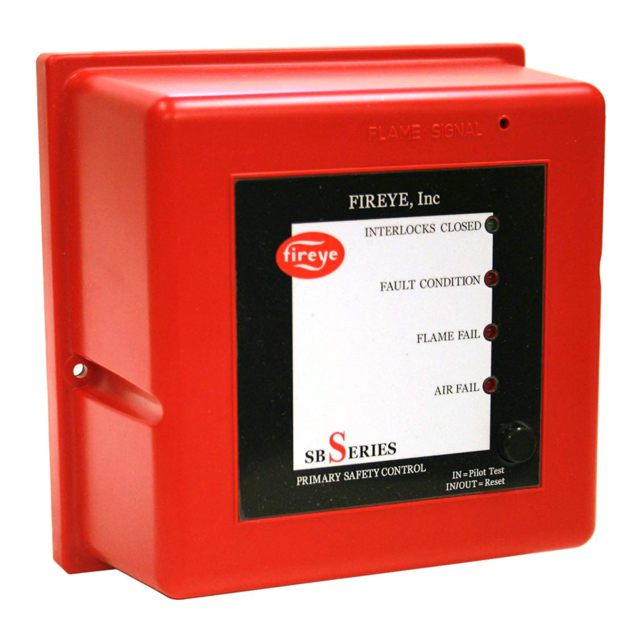
LED indicators are available on the front of the unit that provide current operating status of the burner
system including lockout alarm. A test jack is recessed into the front cover that provides real time
reading of the connected flame sensor. This same test jack is also used to connect to an alpha-numeric
display, SB20896. A push button provides reset from lockout condition as well as placing the unit in a
check condition usable for pilot turn down test.
The
SB
at 120 VAC, 50/60 Hz and 230 VAC, 50/60 Hz making them universally acceptable.
*The wiring base provides a convenient means for connecting field wiring from the burner and valve
system to the control unit. There are three styles of bases: an internal terminal base that provides a
guarded wiring compartment; an external terminal base for use within a protective control panel; and
an expanded external terminal base for use with the modulation sequence control units.
Sensors that may be used with the
scanners, and self-checking UV scanners for continuous operation. Four types of non self-checking UV
scanners meet the demands of various environmental conditions.
© 2021 Carrier
Series Flame Safeguard Control is a compact, microprocessor based, modular burner
SB
Series are tested to EN298.
Series flame safeguard control family are of plug-in design and available in models that operate
Series include flame rod (rectified ionization), ultra-violet (UV)
SB
June 14, 2021
FLAME SAFEGUARD
CONTROLS
SB-2501
1
Advertisement
Table of Contents

Subscribe to Our Youtube Channel
Related Manuals for Fireye SB Series


Summary of Contents for Fireye SB Series
- Page 1 Inappropriate application of this product could result in an unsafe condition hazardous to life and property. DESCRIPTION The Fireye Series Flame Safeguard Control is a compact, microprocessor based, modular burner management system designed to provide automatic ignition and continuous flame monitoring for com- mercial sizes of heating and process equipment firing any type of fuel.
- Page 2 WARNING: This equipment generates and can radiate radio frequency energy, and if not installed and used in accordance with the instruction manual may cause interference to radio communications. It has been tested and found to comply with the limits for a Class A computing device pursuant to Subpart J of part 15 of FCC Rules, which are designed to pro- vide reasonable protection against such interference when operated in a commercial envi- ronment.
- Page 3 Flame Safeguard Controls Eclipse Part Fireye Part Description 120 VAC, 5/10 sec tfi, selectable purge, UV amp, pre-purge VF560222AA SB560222AA air check, reset on power 120 VAC, 5/10 sec tfi, selectable purge, UV amp, pre-purge VF560222AB SB560222AB...
- Page 4 Flame Safeguard Controls Eclipse Part Number Eclipse Part Number Description 120 VAC, 5/10 sec tfi, modulation, UV amp, VF560242XB SB560242XB sequence hold, manual reset 120 VAC, 5/10 sec tfi, modulation, FR amp, pre- purge air check, reset on power VF560243AA SB560243AA 120 VAC, 5/10 sec tfi, modulation, FR amp, pre- VF560243AB...
- Page 5 Flame Safeguard Controls Eclipse Part Number Eclipse Part Number Description 240 VAC, 5/10 sec tfi, no purge, UV amp, VF560332XA SB560332XA sequence hold, reset on power 240 VAC, 5/10 sec tfi, no purge, UV amp, SB560332XB VF560332XB sequence hold, manual reset 240 VAC, 5/10 sec tfi, no purge, FR amp, reset on VF560333AA SB560333AA...
- Page 6 Flame Safeguard Controls Eclipse Part Number Eclipse Part Number Description 120 VAC, 5/10 sec tfi, selectable purge, UV amp, VF560522XB SB560522XB sequence hold, manual reset 120 VAC, 10/15 sec tfi, selectable purge, FR amp, VF560523AA SB560523AA pre-purge air check, reset on power 120 VAC, 10/15 sec tfi, selectable purge, FR amp, VF560523AB SB560523AB...
- Page 7 SB49602-91 SELF-CHECK SCANNER (ECLIPSE) 49600-98 SB49600-98 MAGNIFYING LENS ASSY (ECLIPSE) 49099 SB49099 COUPLING INSUL, 1/2" FNPT Wiring Bases Fireye Part Number Description 22194 SB22194 INTERNAL TERMINAL BASE, PL 22195 SB22195 WIRING BASE, PLASTIC, EXPO 49602-40 SB49602-40 MODULATION BASE (ECLIPSE) Displays ...
- Page 8 DIMENSIONS FIGURE 1. Control Unit, all model Series FIGURE 2. Bases, NO-PURGE and PURGE sequence models Series ¨ P/N: SB22195 P/N: SB22194 © 2021 Carrier...
- Page 9 FIGURE 3. MODULATION sequence model, SB49602-40 Serie ¨ 15/16" FIREYE Inc. (24mm) 6-3/4" (171mm) 1" (25mm) 2 3 4 5 6 7 8 A D S 2S 11 011 12 13 1-9/16" 3/8" (10mm) 3/16" (5mm) (40mm) 8-3/8" (213mm) 4-9/16"...
- Page 10 All wiring should comply with applicable electrical codes, regulations and local ordinances. Use moisture resistant wire suitable for at least 90°C. Good electrical wiring practice should be followed to ensure an adequate ground system. Refer to Fireye Service Note SN-100 separately and General Grounding Rules later in this document for grounding methods.
- Page 11 Terminal 4 - Ignition Wiring The output terminal normally powers a high voltage transformer. Route the high voltage ignition wiring a sufficient distance from all sensors and other low voltage wiring to avoid electrical interfer- ence, which may cause erratic operation of the Series system.
- Page 12 WARNING: Install a modulation sequence model into the modulation style base only; never plug into purge or no-purge bases. FIGURE 5. WIRING FOR NO PURGE MODELS FIGURE 6. WIRING FOR PURGE MODELS © 2021 Carrier...
- Page 13 FIGURE 7. WIRING FOR DIRECT SPARK OF MAIN FLAME, NO PURGE MODELS & PURGE MODLES FIGURE 8. WIRING FOR MODULATION MODULES FIGURE 9. WIRING FOR DIRECT SPARK OF MAIN FLAME, MODULATION MODULES © 2021 Carrier...
-
Page 14: Flame Rod
FIGURE 10.WIRING FOR 120 VAC REMOTE DISPLAY MODULE FIGURE 11. TYPICAL CONNECTIONS FOR ALL MODELS UV/IR FLAME ROD Self Check UV SB49602-91 (Requires 59-504-010) Notes for Figures 5 thr gh 11 1. Ground, shielding & conduit must not be connected to terminal S2. 2. -
Page 15: Operation
OPERATION Introduction This section describes the features of the Series CE. It is presented in three categories: Standard Features, Optional Features, System Errors and Lockout Conditions, and the LED Indicator Lights. Standard Features The following functions are standard features on the Series models as noted. -
Page 16: Dip Switch Selection
DIP SWITCH SELECTION Introduction This section details the location, selection and description of the Series DIP switches which allow for sequence and timing functions as well as system configuration. DIP Switch Location All of the DIP switches are located in the back of each Series unit. -
Page 17: Optional Features
Main Fuel Valve Closed Switch (Terminal V) For NO-PURGE and PURGE sequence models: The Series can be interlocked with the main valve closed position switch. This feature checks the switch position before start-up and after shut-down to insure proper valve operation when the jumper on the base is cut. -
Page 18: Lockout Condition
Manual Reset on Power Outage With "B" specified, the TEST/RESET button must be pressed twice (in and out) to start the sequence. The system error light blinks rapidly (about 4 times per second) and a remote display will show "PUSH RESET TO START". Remote Display A remote di play i... - Page 19 Status Lights and Push-Button All of the status lights and the TEST/RESET push-button are located on the front cover of the Series. This section describes their respective functions. Interlocks Closed This green LED illuminates when the operation limits are made. The limits are wired in series to terminal 7.
- Page 20 © 2021 Carrier...
-
Page 21: Sensor Installation
SENSOR INSTALLATION WARNING: Incorrect sensor installation may cause the sensor to generate a false flame sig- nal, causing unburned fuel to collect in the combustion chamber. The result can be explo- sions, injuries and property damage. Be certain that the flame sensor detects only pilot and main flames, not glowing refractory, burner or ignition parts. - Page 22 When Fireye products are combined with equipment manufactured by others and/or integrated into systems designed or manufactured by others, the Fireye warranty, as stated in its General Terms and Conditions of Sale, pertains only to the Fireye products and not to any other equipment or to the combined system or its overall performance.
Need help?
Do you have a question about the SB Series and is the answer not in the manual?
Questions and answers