Table of Contents
Advertisement
Quick Links
®
M-4000
APRIL 16, 2013
FIREYE
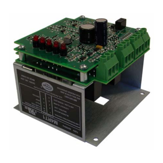
M4RT1
FLAME SAFEGUARD CONTROLS
WARNING: Selection of this control for a particular application should be made by a com-
petent professional, licensed by a state or other government agency. Inappropriate application
of this product could result in an unsafe condition hazardous to life and property.
DESCRIPTION
The Fireye® M4RT1 Flame Safeguard Control is a compact burner management system. It is
designed to provide automatic ignition and continuous flame monitoring for commercial sizes of
heating and process burners that use gaseous fuels.
Flame monitoring is accomplished by a Flame Rod detector, the built in amplifier and programmer.
Control functions and timing are factory set with onboard jumpers. Functions such as recycle/non-
recycle, purge timing, and pilot trial for ignition (P.T.F.I.) time are determined by the jumpers. Flame
Failure Response Time (F.F.R.T.) is fixed at three seconds. LED indicator lights indicate the operat-
ing status of the control.
In the event of ignition failure, or following a safety shutdown, the unit locks out, activating an
alarm circuit. Cycling the power OFF and back on will reset the control. A manual reset option can
be special ordered. Remote reset (via remote pushbutton) is also available as a special order option.
A detailed description of the programmer sequence is found later in this document. Test jacks are
provided to permit flame signal measurement during operation.
The M4RT1 control incorporates a safety checking circuit that is operative on each start. If flame
(real or simulated) is detected prior to a start or during the purge, the fuel valves will not be ener-
gized, and the unit will lock out.
All M4RT1 controls do not require a wiring base due to the terminals included on the relay board.
See INSTALLATION OF CONTROL, SCANNERS, AND FLAME DETECTORS (page 2) for tem-
perature and wiring requirements.
1
Advertisement
Table of Contents

Related Manuals for Fireye M4RT1


Summary of Contents for Fireye M4RT1
- Page 1 (real or simulated) is detected prior to a start or during the purge, the fuel valves will not be ener- gized, and the unit will lock out. All M4RT1 controls do not require a wiring base due to the terminals included on the relay board. See INSTALLATION OF CONTROL, SCANNERS, AND FLAME DETECTORS (page 2) for tem-...
-
Page 2: Specifications
Power Consumption: 12 VA (Operating) Shipping Weight (Approx.): 2.2 lbs. (1.4kg) Table 2: LOAD RATINGS Fireye Terminal Typical Load Maximum Rating & 120V 60 Hz Pilot valve(s) 125 VA pilot duty (solenoid valve) plus 3 or 4 250 VA (Transformer) -
Page 3: Installation - 69Nd1 Flame Rod
Replaceable Fuse The M4RT1 is designed with a field replaceable fuse. The fuse is located on the printed circuit board. The fuse will blow as a result of an overload condition on Terminals 3, 4 or 5. To replace the fuse, remove power from the system. -
Page 4: Maintenance
If the flame is partly luminous, the electrode tip should extend only to the edge of the flame. It is not necessary to maintain absolutely uninterrupted contact with the flame. It is preferable to angle the rod downward to minimize the effect of sagging and to prevent it from coming in contact with any object. - Page 5 PROGRAMMER JUMPER SETTINGS The M4RT1 has a series of 8 jumpers that are used to configure the Purge timing, Pilot Trial for Igni- tion (PTFI) timing, and recycle or non-recycle operation. Purge Timing Jumpers JP1 through JP5 are used to select the Purge timing for the M4RT1.
-
Page 6: Led Indicator Lights
Pilot Trial for Ignition Jumpers JP6 and JP7 are used by the factory only to select the PTFI for the M4RT1. The available PTFI timing selections are 5 and 10 seconds. The factory set, default PTFI time is 10 seconds (JP6 installed, JP7 not installed). - Page 7 ® In the event the pilot flame is not detected by the end of trial for ignition period (PTFI), the pilot gas valve (Terminal 3) and spark ignition (Terminal 4) are de-energized. A safety shutdown occurs followed in approximately 30 seconds by a safety lockout that de-energizes the blower motor (Terminal 8) and energizes the lockout alarm circuit (Alarm LED lighted).
-
Page 8: Timing Chart
INSTALLATION TESTING Use of Test Meter Testing the Fireye M4RT1 Control requires the use of a test AC-DC multimeter, with a 1,000 ohm/ volt DC rating or greater, or a digital meter with 500K input impedance or greater. With the test meter on the DC scale, and the test meter leads inserted into the test jacks. A steady DC voltage reading of 6 to 18 volts should be obtained when the control is detecting flame, and zero volts when no flame is present. - Page 9 ® Minimum Pilot Test This test insures that the flame detector will not sense a pilot flame too small to light the main flame reliably. It must be made on every new installation as well as following the repositioning of the flame detector.
- Page 10 CAUTION: When powered, 260 VAC across S1, S2. CAUTION: Control wiring procedures which deviate from those shown in the diagrams may bypass safety functions designed in the control. Check with the Fireye Representative before deviating from the recommended wiring diagrams.
- Page 11 Use moisture resistant wire suitable for at least 90C. CAUTION: Control wiring procedures which deviate from those shown in the diagrams may bypass safety functions designed in the control. Check with the Fireye Representative before deviating from the recommended wiring diagrams.
- Page 12 Fireye warranty, as stated in its General Terms and Conditions of Sale, pertains only to the Fireye products and not to any other equipment or to the combined system or its overall performance.
Need help?
Do you have a question about the M4RT1 and is the answer not in the manual?
Questions and answers