Advertisement
Quick Links
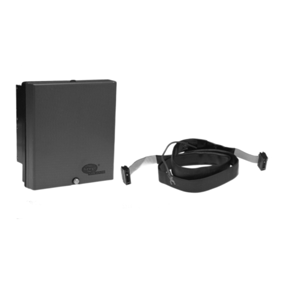
E300 CONTROL
DESCRIPTION
The FIREYE
FLAME-MONITOR System. The Expansion Module connects to any EB700 FLAME-MONITOR
Chassis by means of a ribbon cable. (P/N E350-3, E350-6).
By wiring any of sixteen interlock switches into the Expansion Module, the FLAME-MONITOR
display automatically acts as a "first-out" annunciator for these interlocks. In addition, a fuel selection
circuit is standard. The E300 is shipped with default messages associated with each set of terminals.
The user has the ability to modify these lockout messages in one of two ways:
1.
Use the ED510 display module to select a lockout alarm message for the individual terminals of
the E300 from a library of available messages. Refer to Bulletins E-1101 or ED-5101 (E300
MESSAGE SELECT section).
2.
Program a customized message (up to 40 characters in length) for the individual terminals of the
E300 using an IBM compatible PC with the E300 programming software (available at no charge
from Fireye) and the appropriate hardware. On most PC's Windows Hyperterminal can be used to
program E300 messages.
Note: Modifying the E300 messages requires an EP Programmer with an Engineering code of 28 or
later (Engineering codes are found after the date code, e.g. 9416-28).
The Expansion Module does not interfere with the normal operation of the FLAME-MONITOR
System. It expands the message and diagnostic capability.
The E300 expansion module provides operational information and reduces troubleshooting time and
expense. It expands the standard display messages of the FLAME-MONTOR to identify the specific
limit in the operating control circuit or running interlock circuit which caused the burner shutdown or
lockout. For a detailed description of the FLAME-MONITOR System, see Bulletin E-1101.
APPROVALS
Underwriters Laboratories Inc.: Listing, File #MH10808
Canadian Standards Association: LR7989/17617 Certification Record
Factory Mutual (FM): Approved
SPECIFICATIONS
Supply Voltage:120V (+ 10% - 15%), 50 / 60 Hz
Ambient Temperature Levels: -40 F to +125 F (-40 C to +50 C)
Response Time:170 milliseconds Purge/32 milliseconds Run
Weight:
Humidity: 85% R.H. non-condensing
E350 RIBBON CABLE
E300 Expansion Module provides increased interlock supervision capability of the
0.5 lb.
FIREYE
EXPANSION MODULE
FLAME-MONITOR ™ Control
U L
US
C
APPROVED
LISTED
E-3001
APRIL 8, 2013
E300
®
For use with the Fireye
Advertisement

Related Manuals for Fireye E300


Summary of Contents for Fireye E300
- Page 1 “first-out” annunciator for these interlocks. In addition, a fuel selection circuit is standard. The E300 is shipped with default messages associated with each set of terminals. The user has the ability to modify these lockout messages in one of two ways: Use the ED510 display module to select a lockout alarm message for the individual terminals of the E300 from a library of available messages.
-
Page 2: Ordering Information
3 foot ribbon connector cable E350-6 6 foot ribbon connector cable EC485 RS232 to RS485 converter with power supply. Required to customize E300 lockout alarm messages. ED512-2, -4, -8 Cable with RJ12 connectors on each end. Required to customize E300 lockout alarm messages. -
Page 3: Operation
Any interlock in the 3-P or in the L1-13 circuit that opens for at least 33-50 ms while the burner is ON, or for at least 170 ms while the unit is in PURGE will cause the E300 and the FLAME-MONI- TOR control to respond with the proper message. -
Page 4: Special Notes On Operation
FLAME-MONITOR control. When the switch is in the OIL position, the 2 gas interlocks are ignored. CAUTION: E300 wiring should not interfere with the safety function of the operation inter- lock. Check each interlock for proper operation after wiring the E300. - Page 5 ® WIRING DIAGRAM FOR DEFAULT MESSAGES...
- Page 6 SPECIAL NOTES ON OPERATION An important safety feature of the FLAME-MONITOR system is its ability to remember the proper timed operation of critical terminals such as fuel valve terminals 5, 6 & 7. Jumpering these terminals could cause the control to sense an unusual condition and lock out. When changing fuels on combination burners where direct spark ignition is used, it is normal to jumper terminal 6 to 7.
-
Page 7: Installation And Wiring
® INSTALLATION AND WIRING CAUTION: Remove all power from the FLAME-MONITOR control and the E300 Module before proceeding. Remove cover by loosening screw 1/4 turn. Pull bottom out and lift up from top of clip. Mounting screw is used to attach the control Caution: Route the ribbon cable to its wiring base (60-1950). - Page 8 CUSTOMIZING E300 MESSAGES The user can customize the lockout alarm message associated with each pair of terminals of the E300 Expansion Module. Each customized message can be up to 40 characters in length. Note: Messages longer than 16 characters in length will scroll across the ED510 display. Messages longer than 8 characters will scroll across the ED500 display.
- Page 9 PROGRAMMING THE E300 MESSAGES - EXAMPLE: To change the message associated with the first limit in the 3-P running interlock circuit (termi- nal 3 of the EB700 or E110 and terminal 23 of the E300), type in .T23 and press RETURN. The screen will display: NONE STORED (If no customized message has been programmed for these terminals.
- Page 10 Type in N REVIEW CUSTOMIZED MESSAGES The E300 software will store the last 32,000 bytes of data in RAM memory on the computer. The user can scroll backward or forward through previously entered commands and customized mes- sages by using the Page Up/Page Down/Up Arrow/Down Arrow keys.
- Page 11 MESSAGES The following is a list of default messages which appear on the ED510 display when it is connected to an E300. The user also can modify the message associated with each set of terminals in one of two ways: Use the ED510 display module to select a lockout alarm message for the individual terminals of the E300 from a library of available messages.
- Page 12 The high gas pressure switch has opened and the control is waiting until HOLD PURGE the condition corrects itself. (Terminal 27) 3-P HIGH GAS PRESSURE HOLD MESSAGES DESCRIPTION The high temperature switch has opened and the control is waiting until HOLD PURGE the condition corrects itself.
- Page 13 ® STANDBY MESSAGES DESCRIPTION The auxiliary limit switch #1 in the operating control circuit has opened STANDBY L1-13 AUX. #1 OPEN and the control is waiting until the condition corrects itself. The control will hold this message indefinitely. (Terminal 21) The auxiliary limit switch #2 in the operating control circuit has opened STANDBY L1-13 AUX.
- Page 14 The fuel selection switch was opened during or at the beginning of an LOCKOUT PURGE operation cycle. (Terminal 25 or 26). 3-P FUEL SELECTED The Flame-Monitor programmer has detected an error in attempting to LOCKOUT PURGE read the E300 Expansion Module. EXPANSION MODULE...
- Page 15 ®...
- Page 16 Fireye warranty, as stated in its General Terms and Conditions of Sale, pertains only to the Fireye products and not to any other equipment or to the combined system or its overall performance.
Need help?
Do you have a question about the E300 and is the answer not in the manual?
Questions and answers