Table of Contents
Advertisement
Quick Links
14,000
F
P
O
F
OUR
OST
PEN
RONT
A
L
LIGNMENT
S
:
PECIFICATIONS
Lifting capacity
Overall length w/ramps
Overall width
Width between posts
Column height
Lifting height
Maximum wheel base (2 wheel)
Maximum wheel base (4 wheel)
Runway width
Width between runways
Power pack
.
LB
IFT
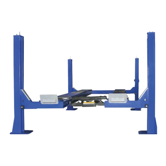
No obstructions! The open front design on our alignment lift allows
total access to front wheel adjustment points and with the cylinder located
under the track, there's no power beam, eliminating risk of damage
to doors and mirrors. (Shown with optional rolling jack and turntables.)
FP 14 KO-A
14,000 lbs.
24' 3"
11' 6"
116"
7' 8"
73"
208"
158"
20"
43"
2hp 220/230 vac 20 amps
FP 14 KO-A
14,000 lb. capacity
Four post
Open front
Alignment lift
Features:
14,000 lb. lifting capacity
Cable drive
Single point pneumatic safety
release mechanism
20" wide non-skid,
diamond plate runways
Powder-coated paint finish
C-channel construction
Hydraulic operation
for minimum maintenance
Three turntable positions for
a wide range of vehicles
Rear slip plates mounted on
ring roller bearings
Fully adjustable lock stops
for easy leveling
Advertisement
Table of Contents

Related Manuals for Tuxedo FP14KO-A


Summary of Contents for Tuxedo FP14KO-A
- Page 1 14,000 RONT LIGNMENT No obstructions! The open front design on our alignment lift allows total access to front wheel adjustment points and with the cylinder located under the track, there’s no power beam, eliminating risk of damage to doors and mirrors. (Shown with optional rolling jack and turntables.) FP 14 KO-A 14,000 lb.
- Page 2 FP14KO-A 14,000 lb Capacity Open Front Alignment Lift ASSEMBLY & OPERATION MANUAL...
- Page 4 14,000 RONT LIGNMENT No obstructions! The open front design on our alignment lift allows total access to front wheel adjustment points and with the cylinder located under the track, there’s no power beam, eliminating risk of damage to doors and mirrors. (Shown with optional rolling jack and turntables.) FP 14 KO-A 14,000 lb.
- Page 5 There is no other express warranty on the Tuxedo lifts and this warranty is exclusive of and in lieu of all other warranties, expressed or implied, including all warranties of merchantability and fitness for a particular purpose.
-
Page 6: Specifications
INTRODUCTION Model FP14KO-A is a four-post lift is used in wheel alignment, vehicle inspection and maintenance for various types of cars and light trucks. Features: - Open front end for easy access car servicing - Multi-position cut-out for turntables (optional part) and extra long rear slip plates to accommodate a wide range of vehicles. - Page 7 Note: All d imensions typical Fig. 1...
- Page 8 TOOLS REQUIRED IN INSTALLATION Rotary hammer drill or similar 3/4” Masonry bit Hammer 4 foot level Open-end wrench set : 7/16” – 1-1/8” Socket and ratchet set: 7/16” – 1-1/8” Hex-key / Allen wrench set Medium crescent wrench Medium pipe wrench Crow bar Chalk line Medium flat screwdriver...
-
Page 9: Installation
INSTALLATION IMPORTANT NOTICE These instructions must be followed to insure proper installation and operation of your lift. Failure to comply with these instructions can result in serious bodily harm and void product warranty. Manufacturer will assume no liability for loss or damage of any kind, expressed or implied resulting from improper installation or use of this product. - Page 10 Note: All 4 legs should be level and square. Use the layout dimensions for floor layout purposes only NOTE All models MUST be installed on 3000PSI concrete only confirming to the minimum requirements. New concrete must be adequately cured by at least 28 days minimum. STEP 4: (Locate the parts) 1.
- Page 11 9. Mount on the plastic slide blocks on the crossbeam.( Fig. 6) 10. Fix the lower end of the safety rack by a bolt. (Fig 7) Fig 4 Fig. 5 Fig. 6 Fig. 7 STEP 6: (front yoke ) Lay down the front columns. Take out the safety rack. Take off the cable sheaves of the front yokes.
- Page 12 Fig. 8 Fig. 9 STEP 9: (check again ) Raise the platform a little by pushing the up button on the power unit. Check the location of all the columns again. Make sure everything is OK. Again using the base plate of the column as guide, drill all the holes for anchoring. Anchor all the columns using bolts supplied.
-
Page 13: Operation
OPERATION RAISE-LIFT 1. Press button on power unit The latch mechanism will ‘trip over’ when the lift raises and drop into each latch stop. But, to lock the lift you must press the lowering handle to relieve the hydraulic pressure and let the latch set tight in a lock position. -
Page 14: Maintenance Schedule
MAINTENANCE SCHEDULE The following periodic maintenance is the suggested minimum requirements and minimum intervals; accumulated hours or monthly period, which ever comes sooner. If you hear a noise or see any indication of impending failure - cease operation immediately – inspect, correct and / or replace parts as required. - Page 15 rvice, contamination levels, filtration, and chemical composition of fluid should be nsidered. If operating in dusty environment shorter interval may be required. The following items should only be performed by a trained maintenance expert. Replace hydraulic hoses Replace cables and rollers. Replace cables and sheaves.
- Page 16 PARTS DRAWING-1...
- Page 17 PARTS DRAWING-2 12 6 38 22 34...
- Page 18 PARTS DRAWING-3...
- Page 19 PARTS DRAWING-4 PART2-B PART1-B PART2-A PART1-A...
- Page 20 PARTS DRAWING-5...
-
Page 21: Parts Drawing
PARTS DRAWING-6 P A R T1-B P A R T1-A PART2-A PART2-B... - Page 22 PARTS DRAWING-7...
-
Page 23: Parts List
PARTS LIST ITEM FCTORY CODE DESCRIPTION NOTE TT5D-400-01-00 pull blade weld assembly TT5D-400-02 idler wheel nylon D16_GB894.1 snap spring TT5D-100-05 spindleⅠ M12x35_GB70 Inner hexangular bolt D20_GB95 flat washer steel TT5D-200-01B-00 ColumnⅡ weld assembly TT5D-200-01A-00 ColumnⅠ weld assembly TT5D-200-02-00 safety blockⅠ weld assembly M10x35_GB5781 hexangular bolt... - Page 24 ITEM FCTORY CODE DESCRIPTION NOTE SGM-802-08 locking plate TT5D-100-12 coverⅡ round steel D30_GB894.1 snap spring TT5D-100-06-02 cylinder pin hexagon slotted nuts M27_GB6179 steel D30_GB95 flat washer TT5D-100-06-03 clip1 TT5D-100-06-04 clip2 D5X80_GB91 snap ring D5X80 TT5D-100-06-01 cylinder TT5D-500-01-00 cross beamⅠ weld assembly TT5.5F4-200-01-10 cover2 nylon...
- Page 25 ITEM FCTORY CODE DESCRIPTION NOTE M16x35_GB5781 hexangular bolt M16X35 D16_GB95 flat washer steel TT5D-600-04-01 protective motherboardⅠ TT5D-600-06 coverⅥ nylon TT5D-600-08 protective motherboardⅡ TT5D-600-02 back plate TT5D-600-01A-00 cross beamⅡ weld assembly TT5D-600-01B-00 cross beamⅢ weld assembly TT5DL-100-20 Steel Cable C TT5DL-100-20 Steel Cable D TT5DL-100-20 Steel Cable B...
-
Page 27: Power Unit Priming Procedure
IMPORTANT POWER UNIT PRIMING PROCEDURE THE PROBLEM: Power unit runs fine but will not pump any fluid. Step 1 – Locate the check valve, the flush plug to the left of the lowering valve. (See drawing below.) Step 2 – Using an Allen wrench and shop towel – with shop towel in place to catch fluid –...
Need help?
Do you have a question about the FP14KO-A and is the answer not in the manual?
Questions and answers