Bromic Heating ECLIPSE SMART-HEAT 3400W Instruction Manual
Electric portable
Hide thumbs
Also See for ECLIPSE SMART-HEAT 3400W:
- Instruction manual (32 pages) ,
- Installation instructions manual (28 pages) ,
- Installation, instruction and service manual (10 pages)

Related Manuals for Bromic Heating ECLIPSE SMART-HEAT 3400W


Summary of Contents for Bromic Heating ECLIPSE SMART-HEAT 3400W
- Page 1 ECLIPSE SMART-HEAT™ ELECTRIC PORTABLE 3400W BY BROMIC INSTRUCTION MANUAL WARNING PLEASE READ AND SAVE THESE INSTRUCTIONS FOR FUTURE REFERENCE VERSION 1.7 EU...
- Page 2 IMPORTANT INSTRUCTIONS This manual contains important information about the installation, operation, and maintenance of Eclipse Smart-Heat Electric Heaters. Please pay close attention to the important safety information shown throughout this instruction manual. Any safety information will be accompanied by the following safety alert symbols DANGER, WARNING, IMPORTANT...
-
Page 3: Table Of Contents
CONTENT IMPORTANT NOTES & WARNINGS PRODUCT OVERVIEW PRODUCT DESCRIPTION PRODUCT SPECIFICATIONS PRODUCT FEATURES HEATER INSTALLATION INSTRUCTIONS 7-20 KEY DIMENSIONS & CLEARANCES BOX CONTENTS WARNING INSTRUCTIONS 10-20 ELECTRICAL INSTALLATION PORTABLE HEATER CONTROL WIRING DIAGRAM OPERATION INSTRUCTIONS 23-26 REMOTE CONTROL FUNCTIONS TURNING THE APPLIANCE ON TURNING THE APPLIANCE OFF PREPARING TO MOVE THE APPLIANCE MOVING THE APPLIANCE... -
Page 4: Important Notes & Warnings
IMPORTANT NOTES & WARNINGS WARNING • The Heater Head has no serviceable parts. For the Base and Arm, please refer to the Maintenance and Servicing section for more details regarding troubleshooting and • IMPORTANT - Installation MUST be carried out by a licensed replacement parts. - Page 5 IMPORTANT NOTES AND WARNINGS CONTINUED • • Do not install the heater directly near a bathtub, shower, Do not lean on heater or rest any objects leaning up against swimming pool or other body of water. Any switches heater, including the arm. or controls must not be within reach of a person in the •...
-
Page 6: Product Overview
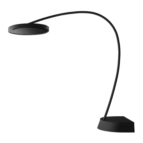
PRODUCT DESCRIPTION The Eclipse Smart-Heat Electric is designed to provide efficient space heating for commercial and residential applications. The Eclipse Smart-Heat Electric heaters have electrical approval in Australia, New Zealand, USA, Canada, Europe, UK, and are rated to IP54 for Ingress Protection, making the Eclipse Smart-Heat Electric Portable the perfect solution for a variety of indoor and outdoor heating applications. -
Page 7: Heater Installation Instructions
HEATER INSTALLATION INSTRUCTIONS - PORTABLE CONTINUED... KEY DIMENSIONS & CLEARANCES Heaters must be installed according to the minimum installation clearances shown in these diagrams. Appliance must not be moved after installation causing the clearance distances to be reduced. Dimensions shown in: mm PORTABLE CEILING &... -
Page 8: Box Contents
HEATER INSTALLATION INSTRUCTIONS - PORTABLE CONTINUED... Contents Packed in (3) Boxes Box 1 Contents Eclipse Head Assembly with 4.5m cable & plug. Including pre-assembled 4 x Dome Head Screws (M4 - Length: 6mm) & 2 x Dome Head Screws (M5 - Length: 14mm) Instruction Manual (This Document) Box 2 Contents... -
Page 9: Warning
HEATER INSTALLATION INSTRUCTIONS - PORTABLE CONTINUED... 4 x Slotted Head Screws (M4 - Length: 6mm) with O-Rings fitted SPARES: 4 x Slotted Head Screws (M4 - Length: 6mm) with O-Rings fitted Box 3 Contents Base Assembly including 10 X Base Weights Note: Plug not shown. -
Page 10: Instructions
HEATER INSTALLATION INSTRUCTIONS - PORTABLE CONTINUED... Instructions For more information, including video instructions, please visit Bromic.com/heat WARNING Heavy Items (>150 kg). Maximum safe lifting 16kg per person. Forklift must be used to move prior to breaking down crate. Using Phillips Head screwdriver, remove 10 X screws to dismantle the Base crate, allowing the Base Cover to be uncovered. - Page 11 HEATER INSTALLATION INSTRUCTIONS - PORTABLE CONTINUED... 3. Remove the Base Cover and place to the side on a non-abrasive surface, to avoid scratching. WARNING Heavy items (10 kg each). Take caution when moving weights. 4. Remove 10 X 10 kg Base weights from the rear compartment of the Heater Base and place them nearby the desired heater location.
- Page 12 HEATER INSTALLATION INSTRUCTIONS - PORTABLE CONTINUED... 5. Remove the 4 x Crate Fixing Screws from the within the Base. WARNING Heavy Item. Min Two Person Lift. Maximum safe lifting 16 kg per person. 6. Remove the Base from the pallet and place it on a flat surface in desired heater location.
- Page 13 HEATER INSTALLATION INSTRUCTIONS - PORTABLE CONTINUED... WARNING Care should be taken when replacing weights into the base. Gloves should be worn to protect hands and fingers from pinch hazards. 8. Replace 10 X 10 kg Base Weights into the rear compartment of the Base.
- Page 14 HEATER INSTALLATION INSTRUCTIONS - PORTABLE CONTINUED... 11. Fasten the front two slots of the Lower Arm section to the dampeners using 2 X M8 Washers, and 2X M8 Nuts. M8 - Nut M8 - Washer 12. Fasten the rear two slots of the Lower Arm section to the Base using 2 X M8 Washers, and 2X M8 - Length: 35mm bolts.
- Page 15 HEATER INSTALLATION INSTRUCTIONS - PORTABLE CONTINUED... 15. Slide the base cover down over the Lower Arm section, allowing it to rest on top of the Base. 16. Unwrap the Top Arm section and the Heater Head from their packaging. 17. Feed the cable through the Top Arm section, and feed through the slack.
- Page 16 HEATER INSTALLATION INSTRUCTIONS - PORTABLE CONTINUED... 19. Fasten the 4 X Dome Head Screws (M4 - Length: 6mm) to the head to lock the angle of the Heater Head relative to the Top Arm section. NOTE: These screws will be used later to adjust the head angle once the heater is fully assembled.
- Page 17 HEATER INSTALLATION INSTRUCTIONS - PORTABLE CONTINUED... WARNING Two person lift. Maximum safe lifting 16 kg per person 24. With the aid of another person, two if possible, feed the Heater Head cable through the Lower Arm, and pull through the cable slack into the base.
- Page 18 HEATER INSTALLATION INSTRUCTIONS - PORTABLE CONTINUED... 26. Using a spirit level and phillips head screwdriver, adjust the angle of the heater head to be level by adjusting the 4 x Dome Head screws (M4 - Length: 6mm) on the heater head.
- Page 19 HEATER INSTALLATION INSTRUCTIONS - PORTABLE CONTINUED... 29. Attach the rubber cable grommet around the cable, and place it in the square slot in the connector box, ensuring the flat face is facing upwards. FLAT FACE - TOP 30. Fasten the Small Connector Box lid using the 4 X Oval Head Screws (#4-40 - Length: 3/8”) #4-40 - Length: 3/8”...
- Page 20 HEATER INSTALLATION INSTRUCTIONS - PORTABLE CONTINUED... 31. Rotate the Base Cover until it is in place covering the Base. 32. Fasten the Base Cover to the Base using the Dome Head Screw (M4 - Length: 6mm). M4 - Length: 6mm bromic.com/heat...
-
Page 21: Electrical Installation
ELECTRICAL INSTALLATION – PORTABLE HEATERS IMPORTANT NOTES & WARNINGS WARNING This heater MUST be installed by an authorised/licenced person. Do not perform maintenance, or carry out installation or assembly procedure while electrical power is switched on. DANGER ELECTRICAL SHOCK HAZARD! Serious injury or death may occur. Disconnect from electrical supply before installing or servicing this heater. -
Page 22: Portable Heater Control Wiring Diagram
PORTABLE HEATER CONTROL WIRING DIAGRAM WIRING DIAGRAM ONLY TO BE INSTALLED & SERVICED BY LICENSED & AUTHORIZED TECHNICIAN. APPLIANCE MANUAL MUST BE READ BEFORE INSTALLING OR SERVICING THIS PRODUCT. Power supply 220-240V - a.c. Minimum Circuit Ampacity 17A (Supplied with heater base). LIVE TILT SWITCH... -
Page 23: Operation Instructions
OPERATING INSTRUCTIONS REMOTE CONTROL FUNCTIONS Heater 100% - Heater output at full (100%) Heater 66% - Heater output at 66% of total Heater 33% - Heater output at 33% of total Heater OFF - Heater off Lights 100% (DIM˄) - Lights output at full (100%) or HOLD to DIM Up Lights 50% - Light output at 50% of total Lights OFF (DIM˅) - Light off or HOLD to DIM Down TURNING THE APPLIANCE ON... -
Page 24: Preparing To Move The Appliance
OPERATING INSTRUCTIONS PREPARING TO MOVE THE APPLIANCE Unplug the supply lead of the appliance from the wall outlet. Remove 1x M4x6mm Screw from Base Top Cover, and rotate the Base Top Cover to expose the Base weights and any floor fastening bolts. Remove any floor fastening bolts from inside the base. -
Page 25: Opening Control Box To Pair A New Remote
OPERATING INSTRUCTIONS OPENING CONTROL BOX TO PAIR A NEW REMOTE WARNING: MUST ONLY BE SERVICED BY LICENSED & AUTHORIZED TECHNICIAN. DANGER ELECTRICAL SHOCK HAZARD! Serious injury or death may occur. Do not touch any components other than specified below. Protective equiment including insulated gloves must be worn. -
Page 26: Pairing Remote Control To Led Pcb
OPERATING INSTRUCTIONS PAIRING REMOTE CONTROL TO LED PCB (BOTTOM 3 BUTTONS OF REMOTE) WARNING: MUST ONLY BE SERVICED BY LICENSED & AUTHORIZED TECHNICIAN. DANGER ELECTRICAL SHOCK HAZARD! Serious injury or death may occur. Do not touch any components other than specified below. Protective equiment including insulated gloves must be worn. -
Page 27: Maintenance & Servicing
MAINTENANCE IMPORTANT NOTES & WARNINGS DANGER ELECTRICAL SHOCK HAZARD! Serious injury or death may occur. Disconnect from electrical supply before servicing this heater. WARNING Servicing and maintenance MUST be carried out by an authorised and licenced service person only. WARNING If the supply cord is damaged, it must be replaced by Bromic, a service agent of Bromic or similarly qualified persons in order to avoid a hazard. -
Page 28: Troubleshooting
TROUBLESHOOTING SYMPTOM POSSIBLE CAUSE (S) CORRECTIVE ACTION No heat 1. Incorrect heater setting chosen 1. Choose heat setting using remote (33%, 66% or 100%). 2. Incorrect Voltage. 2. Connect to 220-240V power supply. 3. No power. 3. Check connection to power supply. 4.
Need help?
Do you have a question about the ECLIPSE SMART-HEAT 3400W and is the answer not in the manual?
Questions and answers