Table of Contents
Advertisement
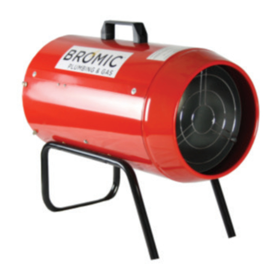
LPG / ULPG MOBILE INDUSTRIAL DIRECT
FIRED AIR HEATER
BY BROMIC
INSTALLATION, INSTRUCTION AND
SERVICE MANUAL
MODELS:
HF15 / HF20 / HF30 / HF50 / HF70
WARNING: THIS HEATER IS APPROVED FOR
Version 6.2 AU/NZ
INDUSTRIAL USE ONLY
IMPORTANT: This heater should be installed and
operated in accordance to the manufacturers
instructions outlined within this manual. The user
shall ensure that local gas fitting regulations,
municipal building codes, AS/NZS 1596
other relevant statutory regulations are adhered
to. Use appliance only in a well-ventilated
space. Read and understand this manual before
attempting to assemble, operate and service the
appliance. Keep this manual for future reference.
and
Advertisement
Table of Contents

Summary of Contents for Bromic Heating HF20
- Page 1 FIRED AIR HEATER BY BROMIC INSTALLATION, INSTRUCTION AND SERVICE MANUAL MODELS: HF15 / HF20 / HF30 / HF50 / HF70 WARNING: THIS HEATER IS APPROVED FOR INDUSTRIAL USE ONLY IMPORTANT: This heater should be installed and operated in accordance to the manufacturers instructions outlined within this manual.
- Page 2 IMPORTANT This manual contains important information about the assembly, operation, and maintenance of Blow Heaters. Please pay close attention to the important safety information shown throughout this instruction manual. Any safety information will be accompanied by the following safety alert symbols: DANGER, WARNING, IMPORTANT...
-
Page 3: Table Of Contents
CONTENTS GENERAL HAZARD WARNING WHEELS ASSEMBLY (FOR HF30/50/70 ONLY) VENTILATION OXYGEN DEPLETION CARBON MONOXIDE (CO) POISONING GUIDELINES OF FUEL GASES OPERATING INSTRUCTIONS START-UP OPERATION SWITCHING OFF THE HEATER EMERGENCY SHUTDOWN SPECIFICATIONS MAINTENANCE AND STORAGE SERVICING INSTRUCTIONS FOR QUALIFIED TECHNICIANS ELECTRICAL COMPONENT SERVICE GAS COMPONENT SERVICE BURNER SERVICE ILLUSTRATED PARTS BREAKDOWN AND PARTS LIST... -
Page 4: General Hazard Warning
GENERAL HAZARD WARNING: IMPORTANT SAFETY GENERAL HAZARD WARNING: INSTRUCTIONS • Failure to comply with the precautions and instructions provided with this heater, can result READ THIS MANUAL CAREFULLY BEFORE in death, serious bodily injury and property loss INSTALLING OR SERVICING THIS PRODUCT. or damage from hazards of fire, explosion, burn, asphyxiation, carbon monoxide poisoning, and/or IMPROPER INSTALLATION, OPERATION, OR... -
Page 5: Guidelines Of Fuel Gases
The hose assembly shall be visually inspected prior • HF15 & HF20 can only be used with a cylinder that to each use of the heater. If it is evident there is uses the LCC27 valve; No adapters are allowed to excessive abrasion or wear, or the hose is cut, it be used. -
Page 6: Start-Up Operation
Be sure that the valve on the gas cylinder has been shut off firmly before disconnection! When MANUAL PIEZO MODELS changing cylinder(s), be sure that the surrounding (HF15/HF20) atmosphere is free from any potential ignition sources. Should there be any gas leakage during operation, •... -
Page 7: Specifications
SPECIFICATIONS For exact appliance specification, please refer to data plate affixed to appliance at the intake side of blow heater. HF 15 HF 20 Model Maximum Heat Output *54 MJ/h *72 MJ/h Gas Consumption 1.08 KG/H 1.44 KG/H Burner type Single gas burner Single gas burner Ignition Type... - Page 8 SPECIFICATIONS CONTINUED... For exact appliance specification, please refer to data plate affixed to appliance at the intake side of blow heater. HF 30 HF 50 HF 70 Model Maximum Heat Output *108 MJ/h *170 MJ/h *242 MJ/h Gas Consumption 2.16 KG/H 3.4 KG/H 4.85 KG/H Burner type...
-
Page 9: Maintenance And Storage
MAINTENANCE AND STORAGE • Keep the heater clean, especially the motor grid and fan blades. This should be done seasonally or sooner if used in dirty operating conditions. • Store the heater in dry, clean and safe place, away from the reach of children. •... -
Page 10: Illustrated Parts Breakdown And Parts List
ILLUSTRATED PARTS BREAKDOWN AND PARTS LIST HF 15/20 - MANUAL MODEL Terminal block REF15/20 MANUAL MODEL SPARE PARTS SCHEDULE Solenoid valve ITEM DESCRIPTION QUANTITY M8 Nut M4 x 25 bolt Thermostat Handle Burner assembly Dished washer Nipple M4 nut Cover Motor grille Injector nozzle 6.3 x 13mm screw... - Page 11 ILLUSTRATED PARTS BREAKDOWN AND PARTS LIST HF 30/50/70 - AUTOMATIC MODEL Cover REF30/50/70 AUTO MODEL SPARE PARTS SCHEDULE Controller Box ITEM DESCRIPTION QUANTITY Cord Grommet Motor assembly Plug & Cord Solenoid valve Handle Indicating Lamp Wheel Flame Detection Needle Terminal block Burner Assembly Rubber bush Igniting Electrode...
-
Page 12: Electrical Schematic
ELECTRICAL SCHEMATIC - MANUAL MODEL HF15/20 AU 1300 276 642 NZ 0508 276 642 | W BROMICPLUMBING.COM | E PLUMBING@BROMIC.COM... - Page 13 ELECTRICAL SCHEMATIC - AUTOMATIC MODEL HF30/50/70 AU 1300 276 642 NZ 0508 276 642 | W BROMICPLUMBING.COM | E PLUMBING@BROMIC.COM...
-
Page 14: Troubleshooting
- Service with qualified person Ignition failed - Hi voltage module defective - Change module Piezo model (HF15 / HF20) - Distance between electrode and - Adjust distance between 3-8mm burner too large. - Set a target temperature higher than ambient...


Need help?
Do you have a question about the HF20 and is the answer not in the manual?
Questions and answers