Bromic Heating ECLIPSE SMART-HEAT ELECTRIC 3400W Instruction Manual
Hide thumbs
Also See for ECLIPSE SMART-HEAT ELECTRIC 3400W:
- Instruction manual (28 pages) ,
- Installation instructions manual (28 pages) ,
- Installation, instruction and service manual (10 pages)

Subscribe to Our Youtube Channel
Related Manuals for Bromic Heating ECLIPSE SMART-HEAT ELECTRIC 3400W


Summary of Contents for Bromic Heating ECLIPSE SMART-HEAT ELECTRIC 3400W
- Page 1 ECLIPSE SMART-HEAT™ ELECTRIC 3400W BY BROMIC INSTRUCTION MANUAL WARNING PLEASE READ AND SAVE THESE INSTRUCTIONS FOR FUTURE REFERENCE VERSION 1.4 EU...
- Page 2 IMPORTANT INSTRUCTIONS This manual contains important information about the installation, operation, and maintenance of Eclipse Smart-Heat Electric Heaters. Please pay close attention to the important safety information shown throughout this instruction manual. Any safety information will be accompanied by the following safety alert symbols DANGER, WARNING, IMPORTANT...
-
Page 3: Table Of Contents
CONTENT IMPORTANT NOTES & WARNINGS PRODUCT OVERVIEW PRODUCT DESCRIPTION SPECIFICATIONS PRODUCT FEATURES KEY DIMENSIONS & CLEARANCES INSTALLATION INSTRUCTIONS - CEILING MOUNTED HEATER 8-14 BOX CONTENTS WARNING INSTRUCTIONS FOR SINGLE POLE OPTIONS 10-11 INSTRUCTIONS FOR TWIN POLE OPTION 12-14 INSTALLATION INSTRUCTIONS - WALL MOUNTED HEATER 15-22 BOX CONTENTS 15-16... -
Page 4: Important Notes & Warnings
IMPORTANT NOTES & WARNINGS WARNING • The Heater Head has no serviceable parts. For the Poles, please refer to the Maintenance and Servicing section for • IMPORTANT - Installation MUST be carried out by a licensed more details regarding troubleshooting and replacement parts. - Page 5 IMPORTANT NOTES AND WARNINGS CONTINUED • Do not install the heater directly near a bathtub, shower, • Do not install heater to an unsecured structure. Mounting swimming pool or other body of water. Any switches surface integrity shall be determined suitable by the installer or controls must not be within reach of a person in the based on weight &...
-
Page 6: Product Overview
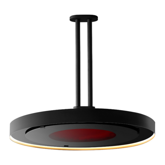
PRODUCT DESCRIPTION The Eclipse Smart-Heat Electric is designed to provide efficient space heating for commercial and residential applications. The Eclipse Smart-Heat Electric heaters have electrical approval in Australia, New Zealand, USA, Canada, Europe, UK, and are rated to IP54 for Ingress Protection, making the Eclipse Smart-Heat Electric Portable the perfect solution for a variety of indoor and outdoor heating applications. -
Page 7: Key Dimensions & Clearances
KEY DIMENSIONS & CLEARANCES Heaters must be installed according to the minimum installation clearances shown in these diagrams. Dimensions shown in: mm PENDANT & WALL MOUNT The stated clearance to combustible materials represents surface temperature of 65°C above room temperature. Building material with a low heat tolerance (such as plastic, vinyl siding, canvas, tri-ply etc.) may subject to degradation at lower temperature. -
Page 8: Installation Instructions - Ceiling Mounted Heater
INSTALLATION INSTRUCTIONS - CEILING MOUNTED HEATER Contents Packed in (3) Boxes Box 1 Contents Eclipse Head Assembly Including pre-assembled 2 x Dome Head Screws (M4 - Length: 6mm) Instruction Manual (This Document) Box 2 Contents Pendant Pole Assembly one of the following styles: •... -
Page 9: Warning
INSTALLATION INSTRUCTIONS - CEILING MOUNTED HEATER CONTINUED... Box 3 Contents Eclipse Pendant Control Remote control (with wall holder and screws) Tools/Parts Required (not Included) • Bolts for fastening to Ceiling surface • Phillips Head Screw Driver • Step Ladder • 2 strong people to help with lifting &... -
Page 10: Instructions For Single Pole Options
INSTALLATION INSTRUCTIONS - CEILING MOUNTED HEATER CONTINUED... Instructions for Single Pole options, including: • Curved Ceiling Mount Pole 610mm • Straight Ceiling Mount Pole 203mm • Straight Ceiling Mount Pole 610mm • Straight Ceiling Mount Pole 1219mm Unpack all items from shipping cartons and place items on a non-abrasive surface. - Page 11 INSTALLATION INSTRUCTIONS - CEILING MOUNTED HEATER CONTINUED... WARNING Heavy Item. Min Two Person Lift. Maximum safe lifting 16 kg per person. 5. Feed the cable through the Ceiling Mount Pole until it has passed through and out into the roof cavity. Feed through the cable slack, and with the help of a second person, lift the Heater Head upwards closer to the Ceiling Mount Pole.
-
Page 12: Instructions For Twin Pole Option
INSTALLATION INSTRUCTIONS - CEILING MOUNTED HEATER CONTINUED... Instructions for Twin Pole option: • Twin Straight Ceiling Mount Pole 610mm Unpack all items from shipping cartons and place items on a non-abrasive surface. 2. Fasten the Twin Pole Roof Bracket on the ceiling in the desired location, using appropriately sized and type bolts (not included) for the mounting surface. - Page 13 INSTALLATION INSTRUCTIONS - CEILING MOUNTED HEATER CONTINUED... 4. Slide the Twin Pole Cap upwards and attach the it to the Twin Pole Roof Bracket using 2 X Dome Head Screws (M4 - Length: 6mm). M4 - Length: 6mm WARNING Heavy Item. Min Two Person Lift. Maximum safe lifting 16 kg per person.
- Page 14 INSTALLATION INSTRUCTIONS - CEILING MOUNTED HEATER CONTINUED... 6. Insert the Heater Bracket into the Twin Straight Ceiling Mount Pole by hooking the attached 2X Dome Head Screws (M4 - Length: 6mm) into the slot feature in the Pole. Fully insert additional 2 X Dome Head Screws (M4 - Length: 6mm) on both sides, and tighten all four screws, to lock heater in place.
-
Page 15: Installation Instructions - Wall Mounted Heater
INSTALLATION INSTRUCTIONS - WALL MOUNTED HEATER Installation Instructions – Wall Mounted Heater Box 1 Contents Eclipse Head Assembly Including pre-assembled 2 x Dome Head Screws (M4 - Length: 6mm) Instruction Manual (This Document) Box 2 Contents Wall Mount Pole Wall Bracket Wall Bracket Cover bromic.com/heat... - Page 16 INSTALLATION INSTRUCTIONS - WALL MOUNTED HEATER CONTINUED... 1 x Round Head Hex Screw (M8 - Length: 15mm) 2 x Dome Head Screw (M6 - Length: 10mm) 1 x Dome Head Screw (M4 - Length: 10mm) 2 x Dome Head Screws (M4 - Length: 6mm) 1 x M20x1.5 Blanking Plug Box 3 Contents...
-
Page 17: Warning
INSTALLATION INSTRUCTIONS - WALL MOUNTED HEATER CONTINUED... WARNING This heater MUST be installed by an licensed electrical contractor. Do not perform maintenance, or carry out installation or assembly procedure while electrical power is switched on. Wait 2 hours after switching off the heater before handling. For longest product life and to maintain product appearance, position heater under cover and protect from rain and weather. -
Page 18: Instructions For Wall Mounted Option
INSTALLATION INSTRUCTIONS - WALL MOUNTED HEATER CONTINUED... Instructions for Wall Mounted option: Unpack all items from shipping cartons and place items on a non-abrasive surface. 2. Mount the Wall Bracket on the wall in the desired location, using appropriately sized and type bolts (not included) for the mounting surface. - Page 19 INSTALLATION INSTRUCTIONS - WALL MOUNTED HEATER CONTINUED... 4. Fasten the Wall Bracket Cover using 1 X Dome Head Screw (M4 - Length: 10mm). M4 - Length: 10mm 5. Feed the cable through the end of the Wall Mount Pole until it has passed through and out the end of the Pole.
- Page 20 INSTALLATION INSTRUCTIONS - WALL MOUNTED HEATER CONTINUED... 6. Insert the Heater Head Bracket into the Wall Mount Pole by hooking the attached 2X Dome Head Screws (M4 - Length: 6mm) into the slot feature in the Pole. NOTE: Heater head should be positioned so that the bromic logo on the glass is at the front of the heater (furtherst away from the wall).
- Page 21 INSTALLATION INSTRUCTIONS - WALL MOUNTED HEATER CONTINUED... WARNING Heavy Item. Min Two Person Lift. Maximum safe lifting 16 kg per person. 8. Attach the Wall Mount Pole to the Wall Bracket. Feed the cable through the back slot of the Wall Mount into the wall cavity, or alternatively, the cable can be fed out of the optional Cable Slot in the underside of the Wall Bracket.
- Page 22 INSTALLATION INSTRUCTIONS - WALL MOUNTED HEATER CONTINUED... 10. Lock the angle of the Wall Mount Pole to the Wall, using 2 X Dome Head Screw (M6 - Length: 10mm). The Wall Bracket angle can be adjusted up to 45° from the wall on each side.
- Page 23 ELECTRICAL INSTALLATION – PENDANT HEATERS IMPORTANT NOTES & WARNINGS WARNING This heater MUST be installed by an authorised/licenced person. Do not perform maintenance, or carry out installation or assembly procedure while electrical power is switched on. DANGER ELECTRICAL SHOCK HAZARD! Serious injury or death may occur. Disconnect from electrical supply before installing or servicing this heater.
-
Page 24: Electrical Installation - Pendant Heater Controls
ELECTRICAL INSTALLATION – PENDANT HEATERS CONTROL IMPORTANT The controller must be installed in a space with free and open air flow which ensures ambient temperature does not exceed 30°C. Open cover to the Pendant Control Box, by removing 6x Oval head screws (#4-40 - Length: 1/2”) from the cover. - Page 25 ELECTRICAL INSTALLATION – PENDANT HEATERS CONTROL 3. Refit cover to the box, ensuring the 6 X M3 O-Rings are present on the 6x Oval head screws (#4-40 - Length: 1/2”). #4-40 - Length: 1/2” (Preassembled) M3 - O-Ring (Preassembled) DANGER The Power source MUST NOT be live when installing the Eclipse Control Box.
-
Page 26: Pendant Heater Control Wiring Diagram
PENDANT HEATER CONTROL WIRING DIAGRAM FOR INSTALLATION USING BROMIC ECLIPSE PENDANT CONTROL (Bromic Eclipse Pendant Control supplied separately) ONLY TO BE INSTALLED & SERVICED BY LICENSED & AUTHORIZED TECHNICIAN. APPLIANCE MANUAL MUST BE READ BEFORE INSTALLING OR SERVICING THIS PRODUCT. Power supply 220-240V - a.c. -
Page 27: For Installation Not Using Bromic Eclipse Pendant Control
PENDANT HEATER CONTROL WIRING DIAGRAM FOR INSTALLATION NOT USING BROMIC ECLIPSE PENDANT CONTROL ONLY TO BE INSTALLED & SERVICED BY LICENSED & AUTHORIZED TECHNICIAN. APPLIANCE MANUAL MUST BE READ BEFORE INSTALLING OR SERVICING THIS PRODUCT. Power supply to suit rated input of transformer (Provided by installer) AC IN LED Transformer... -
Page 28: Operation Instructions
OPERATING INSTRUCTIONS REMOTE CONTROL FUNCTIONS (SUPPLIED WITH BROMIC ECLIPSE PENDANT CONTROL) Heater 100% - Heater output at full (100%) Heater 66% - Heater output at 66% of total Heater 33% - Heater output at 33% of total Heater OFF - Heater off Lights 100% (DIM˄) - Lights output at full (100%) or HOLD to DIM Up Lights 50% - Light output at 50% of total Lights OFF (DIM˅) - Light off or HOLD to DIM Down... -
Page 29: Remote Control Battery
OPERATING INSTRUCTIONS REMOTE CONTROL BATTERY • Keep the batteries out of reach of childrem. • Call a doctor immediately if a battery is swallowed. • Explosion hazard if the battery is substituted incorrectly. • Replace the battery with a CR2430 type battery only. •... -
Page 30: Pairing Remote Control To Led Pcb
OPERATING INSTRUCTIONS PAIRING REMOTE CONTROL TO LED PCB (BOTTOM 3 BUTTONS OF REMOTE). WARNING: MUST ONLY BE SERVICED BY LICENSED & AUTHORIZED TECHNICIAN. DANGER ELECTRICAL SHOCK HAZARD! Serious injury or death may occur. Do not touch any components other than specified below. -
Page 31: Maintenance & Servicing
MAINTENANCE & SERVICING IMPORTANT NOTES & WARNINGS WARNING This heater MUST be installed by an authorised/ licenced person. Do not perform maintenance, or carry out installation or assembly procedure while electrical power is switched on. DANGER ELECTRICAL SHOCK HAZARD! Serious injury or death may occur. Disconnect from electrical supply before installing or servicing this heater. -
Page 32: Troubleshooting
TROUBLESHOOTING SYMPTOM POSSIBLE CAUSE (S) CORRECTIVE ACTION No heat 1. Incorrect heater setting chosen 1. Choose heat setting using remote (33%, 66% or 100%). 2. Incorrect Voltage. 2. Connect to 220-240V power supply. 3. No power. 3. Check connection to power supply. 4.
Need help?
Do you have a question about the ECLIPSE SMART-HEAT ELECTRIC 3400W and is the answer not in the manual?
Questions and answers