Advertisement
Quick Links
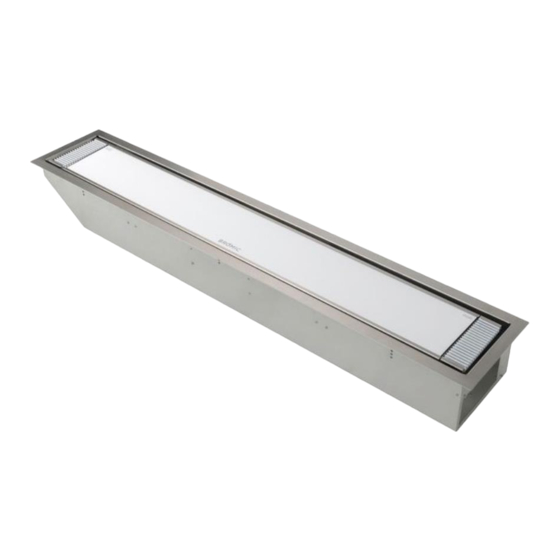
PLATINUM SMART-HEAT™
ELECTRIC HEATERS
BY BROMIC
LOW CLEARANCE (LC) CEILING
RECESS INSTALLATION
INSTRUCTIONS
FOR MODELS 3400 & 2300 W
WARNING
This heater MUST be permanently installed by an
authorised/licenced person. Do not perform
maintenance, or carry out installation or assembly
procedure while electrical power is switched on. Wait 2
hours after switching off the heater before handling.
CEILING RECESS
1x
BOX
TERMINAL BOX
1x
HEATER
NOT INCLUDED
IP COVER
1x
VENT COVER
BLACK
2x
VENT COVER
2x
WHITE
1000mm (39.3") - 3400W
800mm (31.5") - 2300W
bromic.com
WARNING
Joists, beams and rafters shall not be cut or
notched to install the heater.
WARNING
Instructions below are suitable for ceiling surfaces 10-
30mm (0.39"-1.2") thick. For ceiling surfaces thicker
than 30mm (1.2"), contact Bromic for alternative
installation options.
WARNING
The heater shall, under no circumstance, be cov-
ered with insulating material or similar material.
WARNING
It is important that regular maintenance is carried
out on the heater to maintain appearance. Inspect
and clean more frequently in adverse conditions
such as coastal environments.
WARNING
In ceiling recess installation, the heater must be
completely protected against water contact from
above.
CEILING RECESS
2x
MOUNTING BACKET
VENT
VENT
COVER
COVER
TRIM L
TRIM R
2x
2x
N2 WAGO
CONNECTOR
1x
TOOLS REQUIRED
READ THIS MANUAL CAREFULLY. SEE INSIDE
COVER FOR IMPORTANT INFORMATION
ABOUT THIS MANUAL. KEEP INSTRUCTIONS
WITH APPLIANCE FOR FUTURE REFERENCE.
Version 1.4 AU/EU/US
HEATER TRIM
1x
1x M6x10
8x M3x4
4x M4x4
HARDWARE
8mm (5/16")
20mm ( 13/16")
IMPORTANT
1
Advertisement

Related Manuals for Bromic Heating BH3623009


Summary of Contents for Bromic Heating BH3623009
- Page 1 Version 1.4 AU/EU/US WARNING Joists, beams and rafters shall not be cut or notched to install the heater. WARNING Instructions below are suitable for ceiling surfaces 10- PLATINUM SMART-HEAT™ 30mm (0.39”-1.2”) thick. For ceiling surfaces thicker than 30mm (1.2”), contact Bromic for alternative ELECTRIC HEATERS installation options.
-
Page 2: Warning, Important
• The IPX5 marine grade version of the LC Ceiling Recess Kit shall NOT be installed on marine craft. SAVE THESE INSTRUCTIONS SPECIFICATIONS Model LC Ceiling Recess Kit LC Ceiling Recess Kit Marine Part No. US/EU BH3623009 BH3623008 BH3623011 BH3623010 2623009 2623008 2623011 2623010 Total Ouput - Kit +... - Page 3 ISOMETRIC VIEW DEPICTING LOW CLEARANCE RECESS KIT INSTALLATION SETUP OPTIONS The example depicts the recess kit fixed on the length sides only. The installer is responsible for ensuring product is installed in a structurally sound configuration. CEILING MINIMUM 240mm (9.4”) JOIST GAP BETWEEN JOISTS CLEARANCE...
- Page 4 INSTRUCTIONS START HERE 1. Prepare ceiling cut-out (a) with dimensions: 20mm 3400W - 1430mm x 240mm (56.3" X 9.45" 56.3" X 9.45") (13/16") 2300W - 1000mm x 240mm (39.4" X 9.45") Heater must be installed with heater surface at least 2400mm (94") above the finished floor (AFF), with minimum clearance measured from the terminal box end to the nearest surface being 200mm (7.9”).
- Page 5 CEILING RECESS INSTALLATION INSTRUCTIONS CONTINUED ... 20mm 5. Feed the heater cable through the IP cover (h) and (13/16") through the cable gland (f). Attach the IP bracket to the heater using the M6 x 10mm screw (i). When in location, ensure the cable gland (j) is fastened using a 20mm (13/16") spanner.
- Page 6 WIRING DIAGRAM FOR LOW CLEARANCE CEILING RECESS KIT (FOR USE WITH DIMMER OR ON/OFF) BELOW IS A SIMPLIFIED DIAGRAM OF THE TERMINAL BOX. ALL CONNECTIONS ADJUSTED BY THE INSTALLER ARE DISPLAYED. ITEMS NOT DISPLAYED SHALL NOT BE MODIFIED. HEATER CABLE Manual Safety Thermal Switch TOP VIEW OF...
- Page 7 WIRING DIAGRAM FOR LOW CLEARANCE CEILING RECESS KIT (FOR USE WITH 2 HEATERS AND DIMMER OR ON/OFF) BELOW IS A SIMPLIFIED DIAGRAM OF THE TERMINAL BOX. ALL CONNECTIONS ADJUSTED BY THE INSTALLER ARE DISPLAYED. ITEMS NOT DISPLAYED SHALL NOT BE MODIFIED. HEATER HEATER CABLE 2...
- Page 8 WIRING DIAGRAM FOR LOW CLEARANCE CEILING RECESS KIT (FOR USE WITH WALL SWITCH) BELOW IS A SIMPLIFIED DIAGRAM OF THE TERMINAL BOX. ALL CONNECTIONS ADJUSTED BY THE INSTALLER ARE DISPLAYED. ITEMS NOT DISPLAYED SHALL NOT BE MODIFIED. HEATER CABLE Manual Safety Thermal Switch TOP VIEW OF TERMINAL BOX...
- Page 9 CEILING RECESS INSTALLATION INSTRUCTIONS CONTINUED ... 8. Use the supplied 4x M4x4mm screws (l) to close the terminal box. 9. Bring the heater and terminal box (k) up onto stable work platform closer to the terminal box cut-out end. IMPORTANT ENSURE THE FRONT GLASS OF THE HEATER IS PROTECTED BEFORE PLACING ON TOP.
- Page 10 CEILING RECESS INSTALLATION INSTRUCTIONS CONTINUED ... 12. Place the heater in place by alligning the heater mounting plate (c) with heater box mounting support (q). The heater can be rotated in place as shown in the diagram below. 13. Tidy up the heater cable by pushing it through the cable gland (m).
-
Page 11: Mounting Hole
CEILING RECESS INSTALLATION INSTRUCTIONS CONTINUED ... 14. Bring the heater trim in place (r), and align the mounting holes on the trim with the pre-installed 4x M5 hex-flange bolts (s). 5/16" NOTE: MOUNTING HOLES AND BUILT-IN SLOT FOR STEPS 19 & 22 SHOWN BELOW. MOUNTING HOLE BUILT-IN... -
Page 12: Maintenance
ELECTRICAL INSTALLATION WARNING Check product label for correct voltage and wattage to ensure sure power source conforms to This heater MUST be permanently installed by an authorised/ the heaters requirements. licenced person. Do not perform maintenance, or carry out 2. The power cable must positioned away from & installation or assembly procedure while electrical power is switched on.
Need help?
Do you have a question about the BH3623009 and is the answer not in the manual?
Questions and answers