
Related Manuals for Hameg HZ 541


Summary of Contents for Hameg HZ 541
- Page 1 VSWR Messbrücke VSWR Measuring Bridge HZ 541 M A N UA L · H A N D B UC H · M A N U E L...
- Page 2 Änderungen vorbehalten...
-
Page 3: Table Of Contents
VSWR Messbrücke HZ 541 Inhaltsverzeichnis Deutsch ..........CE-Erklärung ........... 4 English ..........Technische Daten ........5 Allgemeines ..........6 Messaufbau ..........7 VSWR-Messbrücke am Spektrum-Analyser HM 5014-2 ..8 Bestimmung des Stehwellen- verhältnisses und des Reflexionsfaktors .. 9 Formeln ..........10 Lieferumfang und Zubehör ...... -
Page 4: Ce-Erklärung
Manufacturer´s name and address Industriestraße 6 Nom et adresse du fabricant D-63533 Mainhausen Die HAMEG GmbH bescheinigt die Konformität für das Produkt The HAMEG GmbH herewith declares conformity of the product HAMEG GmbH déclare la conformite du produit VSWR Messbrücke... -
Page 5: Technische Daten
Technische Daten HZ 541 VSWR-Messbrücke 50 Ohm Mechanische Daten Elektrische Daten Messbrücke: Frequenzbereich: 150 kHz - 1050 MHz Abmessungen: 151,5 x 38 x 29,5 mm Wellenwiderstand: 50 Ohm (B x T x H) (ohne Anschlüsse) Richtverhältnis Gewicht: 450 g 150 kHz - 300 kHz: >28 dB... -
Page 6: Allgemeines
Allgemeines Sofort nach dem Auspacken sollte die Mess- nach schweren Transportbeanspruchun- brücke auf mechanische Beschädigungen gen (z.B. mit einer Verpackung, die nicht und lose Teile im Innern überprüft werden. den Mindestbedingungen von Post, Bahn Falls ein Transportschaden vorliegt, ist sofort oder Spedition entsprach). -
Page 7: Messaufbau
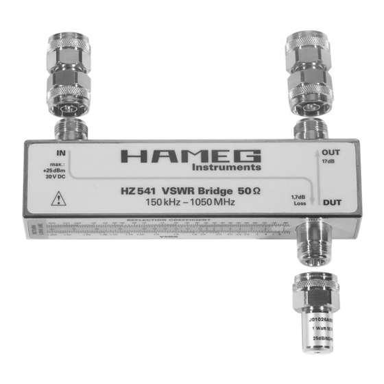
HZ 541 VSWR Bridge 50 1,7 dB 150 kHz – 1050 MHz Loss Prüfobjekt DUT (Device Under Test) Die VSWR Messbrücke HZ 541 besitzt drei DUT-Anschluss (Prüfobjekt) N-Anschlussbuchsen. Das Prüfobjekt sollte möglichst direkt mit diesem Anschluss verbunden werden. Alle IN-Anschluss (Eingang der Messbrücke) -
Page 8: Vswr-Messbrücke Am Spektrum-Analyser Hm 5014-2
VSWR-Messbrücke am Spectrum-Analysator HM 5014-2 IN-Anschluss mit Tracking-Generator (HM OUT-Anschluss (HZ 541) mit Analysator- 5014-2)verbunden (Signalquelle) Eingang (HM 5014-2) verbunden. Benutzt man einen Spektrum-Analysator eines anderen Herstellers muss man an statt der Adapter ein N-Kabel (optoinal) zur Verbindung benutzen. Siehe Zubehörliste. -
Page 9: Bestimmung Des Stehwellen- Verhältnisses Und Des Reflexionsfaktors
Bestimmung des Stehwellenverhältnisses und des Reflexionsfaktors Die Höhe des reflektierten Signals wird über Die VSWR Messbrücke HZ 541 dient zur den „OUT“-Anschluss vom Spektrum-Ana- Bestimmung des Stehwellenverhältnisses lysator gemessen und angezeigt. Der Mess- (VSWR = Voltage Standing Wave Ratio) und wert muss registriert bzw. -
Page 10: Formeln
[male] [male] *) Transportkoffer 1 Stück HZ 526 Kabel, 500 mm, N zu N [male] [male] Benutzer-Handbuch 1 Stück HZ 527 Kabel, 1000 mm, N zu N [male] [male] Garantiekarte 1 Stück *) im Lieferumfang HZ 541 enthalten Änderungen vorbehalten... - Page 11 Änderungen vorbehalten...
-
Page 12: English ............................................... 12 Specifications
VSWR Measuring Bridge HZ 541 Contents Deutsch ..........CE declaration ........4 English ..........Specifications ........13 General remarks ........14 Measurement set-up ......15 VSWR bridge connected to the Spectrum Analyser HM5014-2 ....16 How to determine the VSWR and the Reflection coefficient ...... - Page 13 Specifications HZ541 VSWR Measurement bridge 50 ohms Electrical specifications Mechanical specifications Frequency range: 150 kHz – 1050 MHz Measurement bridge: Impedance: 50 ohms Dimensions (W x D x H): 151.5 x 38 x 29.5 mm Directional ratio: Weight: 450 g 150 kHz - 300 kHz: >28 dB Temperature range: +10 ..
-
Page 14: General Remarks
General remarks After unpacking check for mechanical Operating conditions damage and loose parts floating around inside The permissible operating temperature is the instrument. In case of damage please inform the transport company immediately. +10 ... +40 degr. C. During transport and Do not operate the instrument. -
Page 15: Measurement Set-Up
1,7 dB 150 kHz – 1050 MHz Loss Device Under Test The VSWR bridge HZ 541 has 3 N female DUT = Device under test – connection N-connectors. The DUT should be connected as closely as IN = input to the bridge... -
Page 16: Vswr Bridge Connected To The Spectrum Analyser Hm5014-2
VSWR-Bridge connected to Spectrum-Analyzer HM 5014-2 Connect the OUT terminal of the HZ 541 to Connect the IN input to the tracking generator of the HM 5014-2 (signal source) the input of the analyzer HM 5014-2. In case a spectrum analyzer of another manufacturer is used the adapters have to replaced by N cables (optional). -
Page 17: How To Determine The Vswr And The Reflection Coefficient
How to determine the VSWR and the reflection coefficient The VSWR bridge HZ 541 allows the to B (A>B)“ of the spectrum analyzer. Then measurement of the voltage standing wave switch the spectrum analyzer to the operating ratio (VSWR) and the reflection coefficient mode „A minus B (A –... -
Page 18: Formulae
HZ525 50 ohm load resistor*) 1 ea. warranty document HZ526 Cable, 500 mm, N male to N male HZ527 Cable, 1000 mm, N male to N male *) = included in set of HZ 541 Subject to change without notice... - Page 19 Subject to change without notice...
- Page 20 Oscilloscopes Multimeters Counters Frequency Synthesizers Generators R- and LC-Meters Spectrum Analyzers Power Supplies Curve Tracers HAMEG GmbH Industriestraße 6 D-63533 Mainhausen Telefon: (0 61 82) 800-0 Telefax: (0 61 82) 800-100 E-mail: sales@hameg.de Internet: www.hameg.de Printed in Germany...
Need help?
Do you have a question about the HZ 541 and is the answer not in the manual?
Questions and answers