
Related Manuals for Hameg HM5014-2


Summary of Contents for Hameg HM5014-2
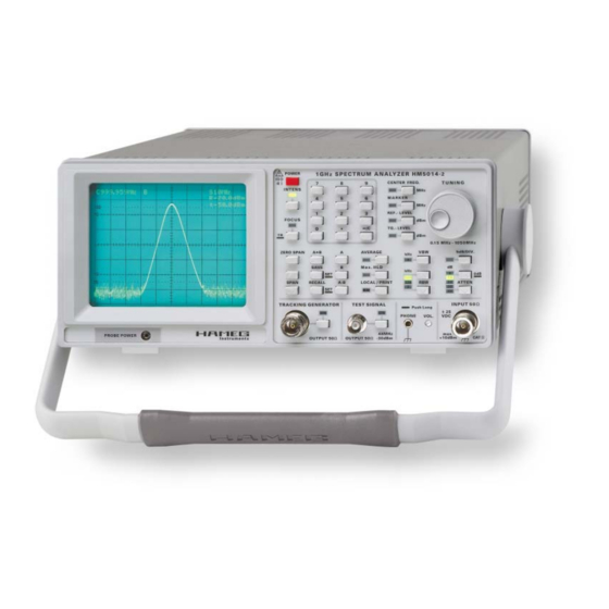
- Page 1 S p e c t r u m A n a l y z e r H M 5 0 1 4 - 2 Service Manual Release: April, 2008...
- Page 2 3. Infl uence on measuring instruments HAMEG instruments fulfi ll the regulations of the EMC directive. The conformity test made by HAMEG is based on the actual generic- and Under the presence of strong high frequency electric or magnetic fi elds, product standards.
-
Page 3: Table Of Contents
2.Performance and Functional Tests 2.1 Test Instructions 2.2 Basic Performance Tests 3. Adjustment 3.1 Preliminary Instructions 3.2 Adjustments 4. Troubleshooting of the HM5014-2 5. Module Replacement 5.1 Opening the instrument 5.2 Replacement of XYZ-Board 5.3 Replacement of interface module 5.4 Replacement of IF-Unit 5.5 Replacement of CPU-Board... - Page 4 H M 5 5 3 0 1 G H z S p e c t r u m A n a l y z e r H M 5 0 1 4 - 2 VSWR Test Unit HZ541 Frequency range from 150 kHz to 1 GHz Amplitude measurement range from -100 dBm to +10 dBm Phase Synchronous, Direct Digital frequency Synthesis (DDS) Amplifier frequency...
-
Page 5: Spectrum Analyzer Hm5014-2
S p e c i f i c a t i o n s Tracking Generator Frequency Range: 0.15 MHz to 1.050 GHz 1 GHz Spectrum Analyzer HM5014-2 Output Level: -50 dBm to +1 dBm Valid at 23 °C after a 30 minute warm-up period Frequency Response (0.15 MHz –... -
Page 6: Basics
1 . B a s i c s 1. Basics 1.1 Block Diagram and Functional Description Subject to change without notice... - Page 7 The 2 attenuators are located between the input / output con- reference signal “DDSFRQ” input via CIC8 from the CPU Board. nectors of the HM5014-2 and the RF Box and the TG Board. Both The frequency range of the “DDSFRQ” signal is from 16 to 28...
- Page 8 RS-232 interface is provided for fl exible highly stable linear regulating circuit. data transfer from and control of the HM5014-2. Also located on the CPU Board is the ASIC for the readout of the spectrum CRT Module...
-
Page 9: Modules And Interconnections
1 . B a s i c s 1.2 Modules and Interconnections TOP VIEW BOTTOM VIEW KEY Module IF unit PS Module RF Box – IF fi lter (with cover) Module PS Module CPU board – RFC board TG Module Module (with cover) CRT Module... -
Page 10: Measurement Equipment And Accessories
This setup is used whenever a signal has to be provided for This setup is used whenever a frequency source inside the the HM5014-2. It is used in multiple steps during checking HM5014-2 is to measured to determine the exact frequency. - Page 11 (M3) This measurement setup is used to determine the power of HM5014-2 TG OUTPUT signals over the entire frequency range of the HM5014-2. The NRVS [M2] is always used with the insertion unit [M3]. NRVS Figure 1.3.3: Measurement SETUP 3...
-
Page 12: Performance And Functional Tests
The operation of the HM5014- 2 is described in detail in the user manual downloadable at the HAMEG website, so it is not repeated here. Only special commands not included in the user manual are described as needed. - Page 13 Connect a 500 MHz, -30 dBm signal (unmodulated) to the RF input of the HM5014-2, as shown in measurement setup 1. Un- plug the SMB connector [CiC2] underneath the RFC board gently Figure 2-3: Adjustment menu on CRT with a pair of pliers [A6].
- Page 14 700 kHz and 1200 kHz. step. The HM5014-2 has the RBW values defi ned as the –6 dB points to follow standard EMC bandwidth defi nitions. Now reconnect the SMB plug [CiC2] to the RFC board. Then...
- Page 15 2.2.12 Check of Audio Output put and to the RF input of the HM5014-2. The marker reading To check the audio output of the HM5014-2, connect a set of PC may be in the range of –27.0 dBm to –33.0 dBm.
-
Page 16: Adjustment
– Allow a minimum warm-up time of 30 minutes at ambient temperature (unit must be inside casing) – Switch off the HM5014-2 and then switch it on again – Set the HM5014-2 to the following: – Center frequency 500 MHz –... - Page 17 3 . A d j u s t m e n t forming a rectangle and a center cross. Also shown is a verti- To adjust the CRT display, use RV3 on XYZ board (see Fig. 3- cal line 1.5 cm from the right vertical side line, which is 6 cm 5) to adjust X-amplitude, P2 (see Fig 3-5) to adjust X-position.
- Page 18 3.2.6 Check of Amplitude adjustment lator) frequency is extremely critical because it depends lar- In order to check the amplitude adjustment, set the HM5014-2 gely on the correct period of warmup with casing on the unit. to the following using measurement setup 1:...
- Page 19 3.2.7 Adjustment of RBW fi lters the displayed level to the level shown on the readout. Vary the The RBW fi lters of the HM5014-2 are not to be adjusted by ser- level from +1 dBm to –10 dBm and check the marker readout vice personnel.
-
Page 20: Troubleshooting Of The Hm5014-2
The following procedures assume that the must be switched off before removing. Before continuing, ob- HM5014-2 is connected to mains / line via a safe- serve the remarks in chapter 2.1 “Test instructions”. ty transformer. Only qualifi ed personnel who are... -
Page 21: Module Replacement
The handle can be removed by pulling it out in position “F“ as shown in fi gure 5-1 and fi gure 5-2. Turn the HM5014-2 to the rear side. Make absolutely sure the unit is not connected to mains! See Fig. 5-4 showing the cable locations. -
Page 22: Replacement Of Interface Module
RiC4 RiC6 RiC9 RiC5 RIC10, RIC11 and WIC2. Take the HM5014-2 into operation (ref. to paragraph. 5.18) 5.3 Replacement of interface module Turn the instrument to the rear. See Fig. 5-2 for orientation, the interface module is the small PCB with the 9 pin SUB-D connector towards the back. -
Page 23: Replacement Of Tracking Generator
TG ATT module in its place and fi x it with the 2 crosshead screws. Place the SMB connector of SiC2 on the SMB jack. In- sert TG module and IF unit (see 5.4 and 5.7). Take the HM5014-2 into operation (ref. to paragraph 5.18) 5.9 Replacement of RF-Box... -
Page 24: Replacement Of Rf Att Module
(CiC3). Then insert the RF box into its position by sliding it on the 5.12 Replacing the front cover SMB connector of the RF ATT box. Turn the HM5014-2 into its nor- mal position. Fix the RF box in place using 4 countersunk screws and make sure it is pushed against the RF ATT while tightening 5.12.1 Removal of the the Front Cover... -
Page 25: Replacement Of The Rf Input Connector / Tg Connector
– Install the XYZ module (see paragraph 5.2.2) – Take the HM5014-2 into operation (see paragraph 5.18). For the fi nal performance test the instrument must be com- pleted and, VERY IMPORTANT, allow a minimum warm up ti- me of 30 minutes at ambient temperature. After that warm up time start with the required adjustments as indicated in table 5.15 Replacement of the RF Input... -
Page 26: Spare Parts Handling
For module replacement some special tools are needed. The- se tools are indicated in table 1-2, item A1, A2, A7 and A8. All these items belong to the Hameg tool kit HM5014-2 and can be ordered under the stock number 29-2000-0045. - Page 27 Subject to change without notice...
- Page 28 Subject to change without notice HAMEG Instruments GmbH © HAMEG Instruments GmbH D-63533 Mainhausen 43-2030-2010 (5) 01042010 Industriestraße 6 A Rohde & Schwarz Company Tel +49 (0) 61 82 800-0 © HAMEG Instruments GmbH D-63533 Mainhausen DQS-Certification: DIN EN ISO 9001:2000 Fax +49 (0) 61 82 800-100 A Rohde & Schwarz Company Tel +49 (0) 61 82 800-0 Reg.-Nr.: 071040 QM sales@hameg.com DQS-Certification: DIN EN ISO 9001:2000 Fax +49 (0) 61 82 800-100 Reg.-Nr.: 071040 QM...
Need help?
Do you have a question about the HM5014-2 and is the answer not in the manual?
Questions and answers