Table of Contents
Advertisement
Available languages
Available languages
Quick Links
TABLE OF CONTENTS
SAFETY INSTRUCTIONS ...........................................................................................................................................................2
Chapter 1 : INTRODUCTION .......................................................................................................................................................5
Chapter 2 : INSTALLATION ........................................................................................................................................................6
Chapter 3 : TECHNICAL DESCRIPTION....................................................................................................................................7
Chapter 4 : STARTING .................................................................................................................................................................8
Chapter 5 : LCD SCREEN DESCRIPTION ..................................................................................................................................9
Chapter 6 : LCD FUNCTIONS DESCRIPTION .........................................................................................................................11
Chapter 7 : THE GENLOCK FUNCTION ..................................................................................................................................13
Chapter 9 : TECHNICAL SPECIFICATIONS ............................................................................................................................15
Chapter 10 : CONTROL SOFTWARE........................................................................................................................................17
Chapter 11 : RS-232 PROGRAMMER'S GUIDE .......................................................................................................................20
WARRANTY...............................................................................................................................................................................43
TABLE DES MATIÈRES
INSTRUCTIONS DE SÉCURITÉ.................................................................................................................................................3
Chapitre 1 : INTRODUCTION ....................................................................................................................................................24
Chapitre 2 : MONTAGE ..............................................................................................................................................................25
Chapitre 3 : DESCRIPTION TECHNIQUE ................................................................................................................................26
Chapitre 4 : MISE EN SERVICE.................................................................................................................................................27
Chapitre 5 : DESCRIPTION DE L'ÉCRAN LCD .......................................................................................................................28
Chapitre 6 : DESCRIPTION DES FONCTIONS DE L'ÉCRAN LCD........................................................................................30
Chapitre 7 : LA FONCTION GENLOCK....................................................................................................................................32
Chapitre 9 : SPÉCIFICATIONS TECHNIQUES ........................................................................................................................34
Chapitre 10 : UTILISATION DU LOGICIEL .............................................................................................................................36
Chapitre 11 : GUIDE DE PROGRAMMATION RS-232............................................................................................................39
GARANTIE .................................................................................................................................................................................43
®
ANALOG WAY
HD SCAN
(XTD920)
User's Manual
Manuel Utilisateur
™
.................................................................................................................................14
™
..............................................................................................................................33
HD SCAN (XTD920)
™
EDITION : 06/05
.
Advertisement
Table of Contents

Related Manuals for Analog way HD SCAN XTD920


Summary of Contents for Analog way HD SCAN XTD920
-
Page 1: Table Of Contents
Chapitre 8 : MISE A JOUR DU HD SCAN ..........................33 Chapitre 9 : SPÉCIFICATIONS TECHNIQUES ........................34 Chapitre 10 : UTILISATION DU LOGICIEL ..........................36 Chapitre 11 : GUIDE DE PROGRAMMATION RS-232......................39 GARANTIE ....................................43 ® ANALOG WAY HD SCAN (XTD920) EDITION : 06/05... -
Page 2: Safety Instructions
HD SCAN™ SAFETY INSTRUCTIONS All of the safety and operating instructions should be read before the product is operated and should be retained for further reference. Please follow all of the warnings on this product and its operating instructions. CAUTION: WARNING: To prevent the risk of electric shock and fire, do not expose this device to rain, humidity or intense heat sources (such as heaters or direct sunlight). -
Page 3: Instructions De Sécurité
HD SCAN™ INSTRUCTIONS DE SÉCURITÉ Afin de mieux comprendre le fonctionnement de cet appareil nous vous conseillons de bien lire toutes les consignes de sécurité et de fonctionnement de l’appareil avant utilisation. Conserver les instructions de sécurité et de fonctionnement afin de pouvoir les consulter ultérieurement. Respecter toutes les consignes marquées dans la documentation, sur le produit et sur ce document. - Page 4 HD SCAN™ SICHERHEITSHINWEISE: Um den Betrieb dieses Geräts zu verstehen, raten wir Ihnen vor der Inbetriebnahme alle Sicherheits und Betriebsanweisungen genau zu lesen. Diese Sicherheits- und Betriebsanweisungen für einen späteren Gebrauch sicher aufbewahren. Alle in den Unterlagen, an dem Gerät und hier angegebenen Sicherheitsanweisungen einhalten.
-
Page 5: Chapter 1 : Introduction
HD SCAN™ ™ HD SCAN Chapter 1 : INTRODUCTION 1-1. SUPPLIED EQUIPMENT ™ • 1 HD SCAN (XTD920). • 1 Set of 19" Brackets. • 1 AC power supply cord. • 1 VGA cable (HD15 male / HD15 male). • 1 CD-ROM (Remote Control Software). •... -
Page 6: Chapter 2 : Installation
HD SCAN™ Chapter 2 : INSTALLATION • Table Top Mounting: The HD SCAN ™ can be used directly on a table: the unit is equipped with 4 plastic feet. ™ • Rack Mounting: The HD SCAN is compatible with a 19" enclosure. Please follow the instructions below to install ™... -
Page 7: Chapter 3 : Technical Description
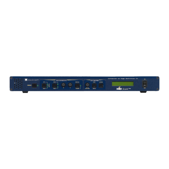
HD SCAN™ Chapter 3 : TECHNICAL DESCRIPTION 3-1. FRONT PANEL FREEZE: Allows to freeze the displayed image. (See also the LCD menu # 4-3). ADJUSTMENTS 4/3 - 16/9 - ZOOM: 4/3, 16/9, or Zoom mode selection. POS / SIZE: Position or Size mode selection. Horizontal Image adjustment. -
Page 8: Chapter 4 : Starting
HD SCAN™ Chapter 4 : STARTING 4-1. CONNECTIONS Connect your computer (Workstation, PC or MAC) to the "COMPUTER INPUT" connector (HD15 female or DVI- ™ I) of the HD SCAN NOTE: The DVI-I connectors (COMPUTER INPUT and MONITOR OUTPUT) are optional. ™... -
Page 9: Chapter 5 : Lcd Screen Description
HD SCAN™ Chapter 5 : LCD SCREEN DESCRIPTION 5-1. INTRODUCTION The LCD screen is composed of 2 modes: the STATUS MODE and the CONTROL MODE. ™ • The STATUS MODE indicates the input and output status of the HD SCAN ™... - Page 10 Chapter 5 : LCD SCREEN DESCRIPTION (continued) HD SCAN™ 5-4. CONTROL MODE The menus of the CONTROL MODE are configured as follow: 1 input menu 1 input status 2 genlock H. ph. 3 SOG input 4 H sync load 75 ohms Hi-Z 2 output menu 1 output status...
-
Page 11: Chapter 6 : Lcd Functions Description
HD SCAN™ Chapter 6 : LCD FUNCTIONS DESCRIPTION 1 [INPUT MENU] + ENTER. [input status] + ENTER. Displays the input status. • [INPUT]: [XGA] = input format. [60 Hz] = input frame frequency. • [GENLOCK]: [none] = genlock signal not detected. [Genlock H. - Page 12 Chapter 6 : LCD FUNCTIONS DESCRIPTION (continued) HD SCAN™ 3 [IMAGE MENU] + ENTER. [flicker filter] + ENTER. Select one of the 8 levels of the anti flicker with and validate with ENTER. [Black Level] + ENTER. Adjust the Black level with + ENTER.
-
Page 13: Chapter 7 : The Genlock Function
HD SCAN™ Chapter 7 : THE GENLOCK FUNCTION 7-1. INTRODUCTION The genlock function allows to synchronize many video equipment in order to mix images together (i.e.: to overlay graphic image onto incoming video) 7-2. CONNECTION 7-3. ADJUSTMENTS Adjust the horizontal phase between the sync generator and the HDTV output, has to be equivalent to 0. Make the adjustment with the LCD menu # 1-2 (genlock H ph). -
Page 14: Chapter 8 : Updating The Hd Scan
™ Switch OFF the HD SCAN (FRONT PANEL SWITCH = O). 8-2. UPDATE INSTRUCTIONS: Open the file "XTD920 updater" (in start/Program/ANALOG WAY/ HD SCAN). Click on "START" on the SOFTWARE. ™ Press the ENTER button of the HD SCAN (FRONT PANEL), and SWITCH it ON simultaneously (FRONT PANEL SWITCH = I ). -
Page 15: Chapter 9 : Technical Specifications
HD SCAN™ Chapter 9 : TECHNICAL SPECIFICATIONS • COMPUTER INPUT Line frequency: Up to 110 kHz. Frame frequency: Up to 130 Hz. Resolution: Up to 1600 x 1280. Sync. types: RGBHV, RGB/S, RGsB (Sync On Green). Levels: R, G, B = 3 x 0.7 Vp/p. H &... - Page 16 Chapter 9 : TECHNICAL SPECIFICATIONS (continued) HD SCAN™ • OTHERS SPECIFICATIONS HDTV clock: 74.250 MHz at 50 Hz & 60 Hz. 74.175824 MHz at 59.94 Hz. Tolerance: ± 30 ppm (internal rate). Holding range: ± 80 ppm (genlock rate). Jitter: 130 psec (0.2 UI;...
-
Page 17: Chapter 10 : Control Software
Turn your computer ON and wait for Windows to completely start. Insert the CD-ROM into your drive: the ANALOG WAY home window will open automatically. Select the language of the CD-ROM menus, then click on "Install a Remote Control Software" and select the name of your device. - Page 18 Chapter 10 : CONTROL SOFTWARE (continued) HD SCAN™ 10-3. SOFTWARE SET UP Select the Serial port in the Controls menu. ™ The HD SCAN is now connected to the control device. Make a Default value (Control menu) if necessary. In the Input menu: - Set the H sync load of the input.
- Page 19 HD SCAN™ Chapter 10 : CONTROL SOFTWARE (continued) 10-3. SOFTWARE SET UP (continued) In Image menu, select the aspect ratio and the under/overscan mode. Then if necessary make the following adjustment: - in the position section: adjust the position and size of the image. - in the color section: adjust the Red, Green, Bleu and Black level.
-
Page 20: Chapter 11 : Rs-232 Programmer's Guide
HD SCAN™ Chapter 11 : RS-232 PROGRAMMER'S GUIDE 11-1. INTRODUCTION If you need to use your own Control Software Program with a PC, MAC or WORKSTATION by a RS-232 port. The ™ HD SCAN allows to communicate by simple transmit or receive ASCII code. ™... - Page 21 HD SCAN™ Chapter 11 : RS-232 PROGRAMMER'S GUIDE (continued) 11-4. COMMANDS AND RESPONSES TABLE The following table resumes commands, which are recognized as valid, and the responses that will be returned to the control device (on RS-232 port). ASCII RESPONSE COMMAND TYPE VALUE...
- Page 22 Chapter 11 : RS-232 PROGRAMMER'S GUIDE (continued) HD SCAN™ 11-4. COMMANDS AND RESPONSES TABLE (continued) ASCII RESPONSE COMMAND TYPE VALUE COMMAND DESCRIPTION MIN MAX DESCRIPTION STATUS COMMANDS UNIT Measures unity in kHz. 65535 This command allows to calculate the 65535 Line frequency (in kHz) = (UNIT VALUE) ÷ input line frequency in kHz (ILD VALUE).
- Page 23 HD SCAN™ Chapter 11 : RS-232 PROGRAMMER'S GUIDE (continued) 11-5. ASCII / HEX / DEC TABLE ASCII ASCII ASCII space " & ’ < > PAGE 23...
-
Page 24: Chapitre 1 : Introduction
HD SCAN™ ™ HD SCAN Chapitre 1 : INTRODUCTION 1-1. MATÉRIEL FOURNI • 1 HD SCAN (XTD920). • 1 Jeu de fixation 19". • 1 Cordon Secteur. • 1 Câble VGA (HD15 mâle / HD15 mâle). • 1 CD-ROM (Logiciel de contrôle à distance). •... -
Page 25: Chapitre 2 : Montage
HD SCAN™ Chapitre 2 : MONTAGE • Montage sur table: ™ Le HD SCAN est directement utilisable sur table. Il est équipé de pieds en caoutchouc. • Montage en baie: ™ ™ Le HD SCAN est compatible avec les baies 19". Pour installer le HD SCAN dans une baie 19", merci de suivre les instructions ci-dessous. -
Page 26: Chapitre 3 : Description Technique
HD SCAN™ Chapitre 3 : DESCRIPTION TECHNIQUE 3-1. FACE AVANT FREEZE: Gel d’image (Actif quand la LED clignote). Voir aussi le menu 4-3 de l'écran LCD. ADJUSTMENTS 4/3 - 16/9 - ZOOM: Sélection des modes 4/3, 16/9 ou ZOOM. POS / SIZE: Sélection des modes "Position"... -
Page 27: Chapitre 4 : Mise En Service
HD SCAN™ Chapitre 4 : MISE EN SERVICE 4-1. RACCORDEMENTS ™ Raccordez votre ordinateur (PC, MAC ou Station de travail) à l’entrée "COMPUTER INPUT" du HD SCAN (connecteur HD15 femelle ou DVI-I) NOTE: Les connecteurs DVI-I sont optionnels (COMPUTER INPUT et MONITOR OUTPUT). ™... -
Page 28: Chapitre 5 : Description De L'écran Lcd
HD SCAN™ Chapitre 5 : DESCRIPTION DE L'ÉCRAN LCD 5-1. INTRODUCTION L'écran LCD est composé de 2 modes : le mode ÉTAT et le mode RÉGLAGE. ™ • Le MODE ÉTAT indique l'état de l'entrée sélectionnée et l'état de la sortie du HD SCAN ™... - Page 29 HD SCAN™ Chapitre 5 : DESCRIPTION DE L'ÉCRAN LCD (suite) 5-4. MODE RÉGLAGE Les menus du MODE RÉGLAGE sont configurés comme ci dessous: 1 input menu 1 input status 2 genlock H. ph. 3 SOG input 4 H sync load 75 ohms Hi-Z 2 output menu...
-
Page 30: Chapitre 6 : Description Des Fonctions De L'écran Lcd
HD SCAN™ Chapitre 6 : DESCRIPTION DES FONCTIONS DE L'ÉCRAN LCD 1 [INPUT MENU] + ENTER. [input status ] + ENTER. Cette fonction affiche l'état de l'entrée. • [INPUT]: [XGA] = format d'entrée. [60 Hz] = fréquence trame d'entrée. • [GENLOCK]: [none] = signal genlock non détecté. [Genlock H. - Page 31 HD SCAN™ Chapitre 6 : DESCRIPTION DES FONCTIONS DE L'ÉCRAN LCD (suite) 3 [IMAGE MENU] + ENTER. [flicker filter] + ENTER. Sélectionnez un des 8 niveaux d'anti-flicker avec et validez avec ENTER. [Black Level] + ENTER. Réglez le niveau de noir avec + ENTER.
-
Page 32: Chapitre 7 : La Fonction Genlock
HD SCAN™ Chapitre 7 : LA FONCTION GENLOCK 7-1. INTRODUCTION La fonction genlock permet de synchroniser plusieurs équipements dans le but de mixer des images ensemble (ex.: pour incruster des images graphiques sur une vidéo) 7-2. RACCORDEMENTS 7-3. RÉGLAGES Réglez la phase horizontale entre le générateur de synchro et la sortie TVHD de façon à être équivalent à zéro. Effectuer les réglages avec le menu 1-2 de l'écran LCD (genlock H ph). -
Page 33: Chapitre 8 : Mise A Jour Du Hd Scan
™ Eteignez votre HD SCAN (INTERRUPTEUR DE LA FACE ARRIÈRE = O). 8-2. INSTRUCTIONS DE MISE A JOUR Ouvrez le fichier "XTD920 updater". (dans Démarrer/Programmes/ANALOG WAY/HD SCAN). Cliquez sur le bouton "START" du logiciel. ™ ™ Maintenez enfoncer le bouton ENTER du HD SCAN... -
Page 34: Chapitre 9 : Spécifications Techniques
HD SCAN™ Chapitre 9 : SPÉCIFICATIONS TECHNIQUES • ENTRÉE INFORMATIQUE "COMPUTER INPUT" Fréquence ligne: Jusqu'à 110 kHz. Fréquence trame: Jusqu'à 130 Hz. Résolution: Jusqu'à 1600 x 1280. Types de Synchro.: RGBHV, RGB/S, RGsB (Synchro sur le vert). Niveaux: R, G, B = 3 x 0,7 Vc/c. Synchro. - Page 35 HD SCAN™ Chapitre 9 : SPÉCIFICATIONS TECHNIQUES (suite) • AUTRES SPÉCIFICATIONS HDTV clock: 74,250 MHz à 50 Hz et 60 Hz. 74,175824 MHz à 59,94 Hz. Tolérance: ± 30 ppm (internal rate). Holding range: ± 80 ppm (genlock rate). Jitter: 130 psec (0,2 UI;...
-
Page 36: Chapitre 10 : Utilisation Du Logiciel
Allumez votre ordinateur et attendez que Windows démarre complètement. Insérez le CD-ROM dans votre lecteur: La page d'accueil ANALOG WAY s'ouvre alors automatiquement. Sélectionnez le langage des menus du CD-ROM, ensuite cliquez sur "Installer un programme de contrôle à distance"... - Page 37 HD SCAN™ Chapitre 10 : UTILISATION DU LOGICIEL (suite) 10-3. ÉCRANS DE CONTRÔLE Sélectionnez le port série dans le menu Controls. ™ Le HD SCAN est maintenant connecté à l'ordinateur. Effectuez un Default value (dans le menu Controls) si nécessaire. Dans le menu Input: - Sélectionnez la charge de la synchro.
- Page 38 Chapitre 10 : UTILISATION DU LOGICIEL (suite) HD SCAN™ 10-3. ÉCRANS DE CONTRÔLE (suite) Dans le menu Image, sélectionnez un aspect ratio et un mode under/overscan. Ensuite, si nécessaire, effectuez les réglages suivants: - dans l'onglet Position: régler la position et la taille de l'image. - dans l'onglet Color: régler les couleurs (Red, Green, Bleu et Black level).
-
Page 39: Chapitre 11 : Guide De Programmation Rs-232
HD SCAN™ Chapitre 11 : GUIDE DE PROGRAMMATION RS-232 11-1. INTRODUCTION Si vous souhaitez utiliser votre propre logiciel de contrôle avec votre PC, MAC ou Station de Travail par un port RS- ™ 232, le HD SCAN peut communiquer par simple émission / réception de caractères ASCII. ™... - Page 40 Chapitre 11 : GUIDE DE PROGRAMMATION RS-232 (suite) HD SCAN™ 11-4. TABLEAU DES CARACTERES DE COMMANDES ET REPONSES Le tableau ci-après donne la liste des commandes qui sont reconnues comme valables et les réponses qui seront retournées à l'appareil de contrôle. VALEUR COMMANDE DESCRIPTION DE LA...
- Page 41 HD SCAN™ Chapitre 11 : GUIDE DE PROGRAMMATION RS-232 (suite) 11-4. TABLEAU DES CARACTERES DE COMMANDES ET REPONSES (suite) VALEUR COMMANDE DESCRIPTION DE LA RÉPONSE TYPE ASCII COMMANDE MIN MAX DESCRIPTION COMMANDES D'ÉTATS UNIT Mesure l'unité en kHz. 65535 Cette commande permet de calculer la 65535 Fréquence ligne (en kHz) = (valeur UNIT) ÷...
- Page 42 Chapitre 11 : GUIDE DE PROGRAMMATION RS-232 (suite) HD SCAN™ 11-5. TABLE ASCII / HEX / DEC ASCII ASCII ASCII espace " & ’ < > PAGE 42...
-
Page 43: Warranty
In case of any problem, get the serial number of the unit, a description of the problem, and then call your authorized dealer. GARANTIE Analog Way garantie le produit contre les défauts matériels et vices de fabrication, pour une période de 3 ans à partir de la date d'achat (retour en nos locaux).
Need help?
Do you have a question about the HD SCAN XTD920 and is the answer not in the manual?
Questions and answers