
Subscribe to Our Youtube Channel
Related Manuals for Analog way VIO 4K


Summary of Contents for Analog way VIO 4K
- Page 1 USER MANUAL USER MANUAL VIO 4K Ref. V701 PROGRAMMER’S GU PROGRAMMER’S GU PROGRAMMER’S GU PROGRAMMER’S GU PROGRAMMER’S GU PROGRAMMER’S GU PROGRAMMER’S GU PROGRAMMER’S GU www.analogway.com...
- Page 2 Information contained in this document, in particular data, pictures, information, trademarks and logos are PROGRAMMER’S GU exclusive property of Analog Way and are protected by copyrights and other intellectual property rights. 2016, Analog Way, all rights reserved – 10/2017 PROGRAMMER’S GU Consequently, any representation and/or reproduction, in part or in full, is prohibited and would be considered a violation of Analog Way’s copyright and other intellectual property rights.
-
Page 3: Table Of Contents
USER MANUAL Table of Contents Introduction ........................7 1.1 Why use the VIO 4K? ..........................7 1.2 VIO 4K at a glance ..........................7 1.3 Key features ............................8 1.4 Inputs ..............................8 1.5 Outputs ..............................8 1.6 Frames ..............................9 1.7 Control .............................. - Page 4 USER MANUAL 5.2 Sending the device to standby ......................31 5.3 Adjusting the front panel ........................32 5.4 Setting up the LAN connection ......................37 5.5 Enabling the USB device connection ....................39 5.6 Using the GPO connection ........................42 5.6.1 What are GPOs? ..........................
- Page 5 USER MANUAL 7.2 Supported inputs (formats and signals) ..................... 96 7.3 Checking your inputs status ........................ 98 7.4 Auto-setting all inputs ........................100 7.5 Setting up an input ........................... 101 7.5.1 Auto-setting the input ....................... 102 7.5.2 Setting up the plug ........................102 7.5.3 Adjusting the image ........................
- Page 6 USER MANUAL 11.2 Creating custom formats ........................207 11.3 Using custom formats ........................211 Presets ........................212 12.1 What is a preset? ..........................212 12.2 Creating presets ..........................212 EDID support ......................216 13.1 What is an EDID ..........................216 13.2 Supported EDIDs ..........................
-
Page 7: Introduction
1 Introduction 1.1 Why use the VIO 4K? The VIO 4K has been designed to convert any content (AV content like a live video, a Power Point presentation, a DVD) from one format to another. With the VIO 4K, you can fully control and operate the conversion environment in a world of multiple PROGRAMMER’S GU... -
Page 8: Key Features
USER MANUAL 1.3 Key features • Up to 9 inputs and 3 independent outputs (7/1 of which native, +2 with the expansion interfaces) • 2 slots for video option card system expansion • 1 slot for audio option card system expansion •... -
Page 9: Frames
USER MANUAL • 6.35mm stereo jack for Headphone • DVI, HDMI & HD15 output plugs available as video loop-through 1.6 Frames • Up to 50 frame memories – Fully resizable • Download/upload via Web RCS • Capture from live inputs/outputs 1.7 Control •... -
Page 10: Technical Specifications
USER MANUAL 1.9 Technical specifications Dimensions (in Rack Units - RU) Operating altitude • • 3000 m / 9842 ft. Dimensions (without rack ears and rear rack mount) Warranty • • W 17.28’’ x H 3.46’’ x D 14.82’’ 3-year warranty on parts and labor back to •... -
Page 11: Safety Instructions
USER MANUAL 2 Safety instructions 2.1 English For optimal use of this device, read all safety and operating instructions before use. Keep the safety and operating instructions for future reference. Please follow all of the warnings on this product and its operating instructions. -
Page 12: French
USER MANUAL 2.2 French Pour une utilisation optimale de cet appareil, nous vous conseillons de bien lire toutes les consignes de sécurité et de fonctionnement avant utilisation. Conservez les instructions de sécurité et de fonctionnement afin de pouvoir les consulter ultérieurement. Respectez toutes les consignes marquées dans la documentation, sur le produit et sur ce document. -
Page 13: Italian
USER MANUAL • RÉPARATION ET MAINTENANCE : L’utilisateur ne doit en aucun cas essayer de procéder aux opérations de dépannage. L’ouverture des appareils par retrait des capots ou de toutes autres pièces constituant les boîtiers ainsi que le dévissage des vis apparentes à l’extérieur, risquent d’exposer l’utilisateur à des chocs électriques ou autres dangers. -
Page 14: German
USER MANUAL - Non far cadere il cavo di alimentazione né appoggiarci sopra degli oggetti pesanti. Se il cavo di alimentazione é danneggiato, spegnere immediatamente l’apparecchiatura. E’ pericoloso far funzionare questa apparecchiatura con un cavo di alimentazione danneggiato, un cavo graffiato puó... -
Page 15: Spanish
USER MANUAL - Das Kabel mittels dem Stecker herausziehen. Niemals am Stromkabel selbst ziehen. - Die Steckdose muß sich in der Nähe des Geräts befinden und leicht zugänglich sein. - Das Stromkabel nicht fallen lassen und keine schweren Gegenstände auf es stellen. Wenn das Stromkabel beschädigt ist, das Gerät sofort abschalten. - Page 16 USER MANUAL Atención: El cable de alimentación constituye el único medio de desconectar el aparato totalmente de la red eléctrica. Para estar seguro de que el aparato no está más alimentado, este cable debe de ser desconectado de la toma de corriente. Aplicar las siguientes consignas: - El material conectado a residencia a la red informática, debe de tener un dispositivo de seccionamiento fácilmente accesible que debe de ser incorporado al exterior del aparato.
-
Page 17: Physical Description
USER MANUAL USER MANUAL USER MANUAL 3 Physical description USER MANUAL 3.1 Front panel USER MANUAL USER MANUAL USER MANUAL USER MANUAL USER MANUAL PROGRAMMER’S GUIDE PROGRAMMER’S GUIDE www.analogway.com PROGRAMMER’S GUIDE... -
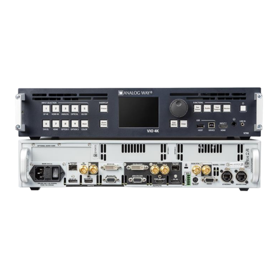
Page 18: Rear Panel
USER MANUAL USER MANUAL USER MANUAL 3.2 Rear panel USER MANUAL USER MANUAL USER MANUAL USER MANUAL USER MANUAL USER MANUAL PROGRAMMER’S GUIDE PROGRAMMER’S GUIDE www.analogway.com PROGRAMMER’S GUIDE... -
Page 19: Programmer's Gu
4 Quick setup & operation 4.1 Front panel control You can quickly control and configure your VIO 4K unit from the VIO 4K unit itself, via the front panel buttons and menu tree. You simply need to switch on the unit to access the front panel menu tree: PROGRAMMER’S GU... -
Page 20: Operating From The Front Panel
USER MANUAL 4.1.2 Operating from the front panel OUTPUT MENU Enter the OUTPUTS menu and select STANDARD OUTPUT to set up the output. Output format and rate: • Choose the format and rate generation mode and then adjust the format settings accordingly. •... - Page 21 VIO 4K - Menu Tree for a complete description of all PROGRAMMER’S GU available buttons and menus. The following graph also provides a quick overview of the VIO 4K operational environment: PROGRAMMER’S GU PROGRAMMER’S GU PROGRAMMER’S GU PROGRAMMER’S GU...
- Page 22 USER MANUAL PROGRAMMER’S GU PROGRAMMER’S GU PROGRAMMER’S GU PROGRAMMER’S GU PROGRAMMER’S GU PROGRAMMER’S GU PROGRAMMER’S GU PROGRAMMER’S GU www.analogway.com...
-
Page 23: Web Rcs Interface
In this web browser, enter the IP address of your VIO 4K (displayed in the front panel LCD screen). The Web RCS connection should start. PROGRAMMER’S GU NOTE: The VIO 4K unit must be ON and operating (i.e. not in standby mode) to be able to connect to the Web RCS client embedded in the device. PROGRAMMER’S GU PROGRAMMER’S GU... - Page 24 Select Apply to save and apply the new settings. (2) Set up the LAN adaptor of your PC: Open your LAN adaptor settings. Assign an IP address to your computer on the same network and subnet as your VIO 4K, for example: •...
-
Page 25: Connecting To The Web Rcs (Usb)
PROGRAMMER’S GU 4.2.2 Connecting to the Web RCS (USB) You can connect to the Web RCS client of your VIO 4K unit using an Ethernet over USB connection. PROGRAMMER’S GU NOTE (Windows users only): You need to install the Ethernet over USB device driver before plugging in the USB cable. - Page 26 (3) Connect to the Web RCS: 1. Open a web browser. 2. In this web browser, type in the VIO 4K virtual IP address (available from the CONTROL > USB Device menu). The Web RCS interface should load into your web browser.
- Page 27 USER MANUAL 2. In this web browser, type in the VIO 4K virtual IP address (available from the CONTROL > USB Device menu). The Web RCS interface should load into your web browser. W7/W8/W8.1/W10 USERS (1) Enable the mass storage USB device connection: 1.
- Page 28 NOTE: You will need to install the driver if the VIO4K USB Ethernet/RNDIS gadget is not available. The driver is now associated to your VIO 4K unit and the VIO 4K will always be recognized as a USB device from now on.
-
Page 29: Operating From The Web Rcs Interface
Web RCS via LAN or via USB, respectively), you can open a web browser and type in the IP address of your VIO 4K unit (displayed in the front panel LCD screen) to access the Web RCS interface: PROGRAMMER’S GU... - Page 30 USER MANUAL TIP: Use the PRECONFIG > Setup Assistant to get started with your setup. EDIT MENU Once your setup is complete, click on the Edit tab to start putting it all together in the screen: • Select the input to display on the output •...
-
Page 31: Device Management
Switch on the VIO 4K power supply button located on the rear panel. NOTE: The VIO 4K will start up in standby mode if you shut down the device in standby mode with the back to standby power loss function enabled (SEE: Back to standby function for details). -
Page 32: Adjusting The Front Panel
Press the ON/OFF button for about 3 seconds. 5.3 Adjusting the front panel The front panel allows you to control and configure the VIO 4K framework directly from the VIO 4K unit itself, via the front panel buttons and the menu tree on the LCD display. - Page 33 USER MANUAL To select the LCD timeout before standby: Caution: Disabling the LCD Standby may shorten the LCD backlight lifespan. Front Panel 1. Enter the CONTROL menu on the Front Panel interface. 2. Scroll down and select Front Panel to access the front panel settings menu. 3.
- Page 34 USER MANUAL To disable the menu page timeout: Front Panel 1. Enter the CONTROL menu on the Front Panel interface. 2. Scroll down and select Front Panel to access the front panel settings menu. 3. Uncheck the Enable Menu Page Timeout check-box to stay on the current menu page whatever the timeout.
- Page 35 USER MANUAL Web RCS 1. Go to the Setup menu on the Web RCS interface. 2. Click on the CONTROL tab to access the device settings and control functions. 3. In the left side toolbar, select Front Panel to access the front panel settings page. 4.
- Page 36 USER MANUAL TIP: Check the Safe Input Select check-box to disable the selection of inputs for which no valid signal has been detected. To disable the selection of inputs without signal: Front Panel 1. Enter the CONTROL menu on the Front Panel interface. 2.
-
Page 37: Setting Up The Lan Connection
USER MANUAL The LAN connection is used by the Web RCS interface to connect to the VIO 4K unit from a PC or tablet via 5.4 Setting up the LAN connection LAN (SEE: Connecting to the Web RCS (LAN) for more information). - Page 38 USER MANUAL To set up LAN manually (entering an IP address): Front Panel 1. Enter the CONTROL menu on the Front Panel interface. 2. Select Connection and then LAN Setup to access the device LAN interface settings menu. 3. Uncheck the Obtain IP via DHCP check-box to disable DHCP (check again to enable). 4.
-
Page 39: Enabling The Usb Device Connection
Connecting to the Web RCS (USB) 5.5 Enabling the USB device connection The USB device connection is used by the Web RCS interface to connect to the VIO 4K unit from a PC or tablet via USB (SEE: Connecting to the Web RCS (USB) for more information). - Page 40 USER MANUAL Web RCS 1. Go to the Setup menu on the Web RCS interface. 2. Click on the CONTROL tab to access the device settings and control functions. 3. In the left side toolbar, select Network to access the device network settings page. 4.
- Page 41 USER MANUAL Web RCS 1. Go to the Setup menu on the Web RCS interface. 2. Click on the CONTROL tab to access the device settings and control functions. 3. In the left side toolbar, select Network to access the device network settings page. 4.
-
Page 42: Using The Gpo Connection
Connecting to the Web RCS (USB) 5.6 Using the GPO connection 5.6.1 What are GPOs? GPOs are a set of outputs that can be used to control a VIO 4K unit from external devices (automation). 5.6.2 ON/OFF pins description PROGRAMMER’S GU Pins 1 and 2 are dedicated to turn on and off the device when a switch is placed in-between. -
Page 43: Gpo Modes
USER MANUAL 5.6.4 GPO modes The mode of the GPO can be set manually or automatically: Manual mode The open/closed state of the GPO is specified manually by user action, either through the Web RCS or the Front Panel interface, or from an external controller. Automatic mode The open/closed state of the GPO is automatically generated right before or right after an input is selected or a take action is performed (right before the transition, at the beginning of the transition... -
Page 44: Resetting The Unit
PROGRAMMER’S GU 5.7 Resetting the unit If you are using the VIO 4K for the first time, you can reset the device to factory settings (as-is out of the box) to start enjoying the unit as a brand new device. - Page 45 USER MANUAL To reset to configuration default values: NOTE: • Network, Web RCS and Link parameters will remain unchanged. • Library frames and logos will not be erased. Front Panel 1. Enter the CONTROL menu on the Front Panel interface. 2.
- Page 46 USER MANUAL Front Panel 1. Enter the CONTROL menu on the Front Panel interface. 2. Scroll down and select Factory Reset (out of the box) to start the factory reset: • Select YES to confirm the reset (/!\ this action is irreversible). •...
-
Page 47: Creating Backups
The VIO 4K allows you to save and export your device configurations, for example to create backup copies of your settings, or to import these settings into other VIO 4K units in order to quickly have a new unit up and running. - Page 48 USER MANUAL Web RCS 1. Go to the Setup menu on the Web RCS interface. 2. Click on the SERVICES tab to access services available on the device. 3. In the left side toolbar, select Import/Export to access the device configuration page. 4.
- Page 49 USER MANUAL To export a configuration: Front Panel 1. Enter the SERVICES menu on the Front Panel interface. 2. Select Device Config to access the device configuration menu. 3. Select Export and choose the export type. Available export types include: FROM DEVICE Export the current device configuration FROM DEVICE...
- Page 50 USER MANUAL Web RCS 1. Go to the Setup menu on the Web RCS interface. 2. Click on the SERVICES tab to access services available on the device. 3. In the left side toolbar, select Import/Export to access the device configuration page. 4.
- Page 51 USER MANUAL To import a configuration: Information: Your device will automatically reboot once the import is complete. Front Panel NOTE: You will need a USB key to import a configuration via the front panel. Before you start: • Plug-in a USB key into the USB HOST port (located in the front panel). •...
- Page 52 USER MANUAL Web RCS 1. Go to the Setup menu on the Web RCS interface. 2. Click on the SERVICES tab to access services available on the device. 3. In the left side toolbar, select Import/Export to access the device configuration page. 4.
-
Page 53: Erasing The Device Memories
USER MANUAL 10. Select Load to Device to load the imported configuration on the device. NOTE: This action will restore your device with the selected categories. Alternatively, you can select Save configuration to device storage to save the imported configuration to the device storage without loading it on the device. SEE also: Saving a configuration to the device storage. - Page 54 USER MANUAL 2. Click on the CONTROL tab to access the device settings and control functions. 3. In the left side toolbar, select Erase Memories to access the erase memories page. 4. Under Erase Input Settings Memories, click on the Start button: •...
- Page 55 USER MANUAL To erase all preset memories: Front Panel 1. Enter the CONTROL menu on the Front Panel interface. 2. Scroll down and select Reset/Erase to access the reset and erase menu. 3. Select Reset Preset Memories to start clearing up the preset bank: •...
- Page 56 USER MANUAL To erase all frames in the library: Front Panel 1. Enter the CONTROL menu on the Front Panel interface. 2. Scroll down and select Reset/Erase to access the reset and erase menu. 3. Select Erase Frame Library to start clearing up the library: •...
- Page 57 USER MANUAL Web RCS 1. Go to the Setup menu on the Web RCS interface. 2. Click on the CONTROL tab to access the device settings and control functions. 3. In the left side toolbar, select Erase Memories to access the erase memories page. 4.
-
Page 58: Updating The Device
USER MANUAL 5.10 Updating the device You can update your VIO 4K unit to enjoy the latest firmware on the device. The updater release information includes: • Updater version; • Executable file name; • Creation date; • Version and Checksums of the different programmable components;... - Page 59 USER MANUAL To update your device: Caution: Do not switch off the unit during the update. The VIO 4K unit will reboot itself once the update is complete. Front Panel NOTE: Before you start: • Back up your settings if necessary.
-
Page 60: Output Management
An output is a group of plugs that deliver the same video content under various signal types. By default, each VIO 4K unit is equipped with one standard output that contains the following plugs: 6.2 Supported outputs (formats and signals) PROGRAMMER’S GU... - Page 61 USER MANUAL Plug type Formats Signals HDMI 1.4a SDTV YCbCr ITU-R BT.601 RGB Full scale (0-255) RGB Limited scale (16-235) EDTV YCbCr ITU-R BT.601 RGB Full scale (0-255) RGB Limited scale (16-235) HDTV YCbCr ITU-R BT.709 RGB Full scale (0-255) RGB Limited scale (16-235) UHDTV/4K YCbCr ITU-R BT.709...
-
Page 62: Additional Outputs Supported With Video Expansion Interfaces
USER MANUAL SEE also: Custom Formats 6.2.1 Additional outputs supported with video expansion interfaces Plug type Formats Signals HDMI 2.0 UHDTV/4K YCbCr ITU-R BT.601, ITU-R BT.709, ITU-R BT.2020 (up to 60Hz) RGB Full scale (0-255) RGB Limited scale (16-235) DisplayPort 1.2 UHDTV/4K YCbCr ITU-R BT.601, ITU-R BT.709, ITU-R BT.2020 (up to 60Hz) - Page 63 USER MANUAL FORMAT NOT SUPPORTED Plug disabled for this output because the format is not supported NO DISPLAY DETECTED Plug is disabled because there is no display detected CONNECTION FAILED (CHECK Plug disabled because connection has failed CABLE) REFERENCE SIGNAL Plug disabled because reference used is not compatible with INCOMPATIBLE plug standard...
-
Page 64: Setting Up The Output
USER MANUAL Alternative method: 1. Go to the Setup menu on the Web RCS interface. 2. Click on the OUTPUTS tab to access the outputs setup page. 3. In the left side toolbar, select General to access the general outputs setup page. 4. - Page 65 USER MANUAL FORMAT NOT Plug is disabled because the display is not compatible with the SUPPORTED BY format parameters DISPLAY • Signal Type: Currently applied signal type (analog plugs). List of possible output signal types (analog plugs): YUV signal 0-700mV RGsB RGB signal with synchro on green (SOG) RGBs...
-
Page 66: Setting Up The Plug
USER MANUAL Web RCS 1. Go to the Setup menu on the Web RCS interface. 2. Click on the OUTPUTS tab to access the outputs setup page. 3. In the left side toolbar, select STANDARD OUTPUT to access the standard output setup page. 4. - Page 67 USER MANUAL To select the signal type for an analog plug: Front Panel 1. Enter the OUTPUTS menu on the Front Panel interface. 2. Select STANDARD OUTPUT to access the standard output setup menu. 3. Select Plug Settings to access the plug setup menu for the output. 4.
- Page 68 USER MANUAL To select the color space for a digital plug: Front Panel 1. Enter the OUTPUTS menu on the Front Panel interface. 2. Select STANDARD OUTPUT to access the standard output setup menu. 3. Select Plug Settings to access the plug setup menu for the output. 4.
- Page 69 USER MANUAL To select the color depth for a digital plug: Front Panel 1. Enter the OUTPUTS menu on the Front Panel interface. 2. Select STANDARD OUTPUT to access the standard output setup menu. 3. Select Plug Settings to access the plug setup menu for the output. 4.
- Page 70 HDMI plugs are compatible with the DVI standard. In some cases, the HDMI plug may even need to work as DVI in order for the source connected to the plug to work properly. The VIO 4K allows you to force the DVI mode on HDMI plugs. To force the DVI mode on an HDMI plug: Information: No audio will be transmitted.
- Page 71 USER MANUAL 6.4.2.3 Choosing the 3G transport mode (SDI and Optical plugs) SDI/Optical plugs can work in 2 levels: • Level A: 1 channel + 1 complete image. • Level B: 1 image in 2 parts (= 2 signals). By choosing the SDI level of the plug (SDI and Optical plugs only), you can specify the standard used to transport 3G formats.
- Page 72 With HDCP enabled (default), the HDCP negotiation is maintained even if the DVI, HDMI or DisplayPort plug is not the current plug (active input). PROGRAMMER’S GU • With HDCP disabled, none of the HDCP sources can be displayed (the sources will see the VIO 4K inputs as non-HDCP compliant). PROGRAMMER’S GU Output control •...
- Page 73 USER MANUAL To enable/disable HDCP on an output plug: Front Panel 1. Enter the OUTPUTS menu on the Front Panel interface. 2. Select STANDARD OUTPUT to access the standard output setup menu. 3. Select Plug Settings to access the plug setup menu for the output. 4.
-
Page 74: Setting Up The Format
6.4.3 Setting up the format The output format determines the final resolution and rate of the output. On the VIO 4K, you can set up the format using one of the following format and rate generation modes: Internal reference mode (default) - Page 75 USER MANUAL To use the internal (clock) reference (default): Front Panel 1. Enter the OUTPUTS menu on the Front Panel interface. 2. Select Standard Output to access the standard output setup menu. 3. Select Format to access the standard output format setup menu. 4.
- Page 76 USER MANUAL Web RCS 1. Go to the Setup menu on the Web RCS interface. 2. Click on the OUTPUTS tab to access the outputs setup page. 3. In the left side toolbar, select Standard Output to access the standard output setup page. 4.
- Page 77 USER MANUAL To auto-set the format using EDIDs: Front Panel 1. Enter the OUTPUTS menu on the Front Panel interface. 2. Select STANDARD OUTPUT to access the standard output setup menu. 3. Select Format to access the standard output format setup menu. 4.
- Page 78 USER MANUAL To framelock to a video reference: Front Panel 1. Enter the OUTPUTS menu on the Front Panel interface. 2. Select STANDARD OUTPUT to access the standard output setup menu. 3. Select Format to access the standard output format setup menu. 4.
- Page 79 USER MANUAL 8. Wait for the Format generation in progress screen to check the new format settings. 9. Once the setup is complete, press the EXIT-MENU button to return to the output setup menu. TIP: Go to the output setup menu and select Framelock Tune to adjust the vertical and horizontal offsets to apply to the output signal.
- Page 80 USER MANUAL To Genlock to the dedicated input: NOTE: All Genlock timings meet broadcast ITU/SMPTE standards. Front Panel 1. Enter the OUTPUTS menu on the Front Panel interface. 2. Select STANDARD OUTPUT to access the standard output setup menu. 3. Select Format to access the standard output format setup menu. PROGRAMMER’S GU 4.
-
Page 81: Adjusting The Aoi (Area Of Interest)
USER MANUAL 5. Under SIGNAL > Format Mode, select GENLOCK to use the Genlock input as a reference to set up the format. 6. If required, adjust the vertical and horizontal offsets to apply to the output signal: • Offset H: Offset in pixels (ratio of 1 line) to apply to the output signal. •... - Page 82 USER MANUAL PROGRAMMER’S GU PROGRAMMER’S GU To automatically fit the AOI to the output format: PROGRAMMER’S GU Front Panel 1. Enter the OUTPUTS menu on the Front Panel interface. 2. Select STANDARD OUTPUT to access the standard output setup menu. PROGRAMMER’S GU 3.
- Page 83 USER MANUAL 5. If required, adjust the Overscan Compensation (as percentage of the output format size). To manually adjust the AOI size and position: Front Panel 1. Enter the OUTPUTS menu on the Front Panel interface. 2. Select STANDARD OUTPUT to access the standard output setup menu. 3.
-
Page 84: Rotating The Output
USER MANUAL • V Position: AOI vertical start offset compared to the output format (in pixels). • V Size: AOI vertical size (in pixels). TIP: Click on the AOI finder and drag the handles to adjust the AOI size and position. Related topics: •... -
Page 85: Correcting The Image
USER MANUAL 6.4.6 Correcting the image You can truly control the final rendering of the output in the screen with the following colorimetry adjustments: • Gamma, • Flicker filter, • Brightness, • Contrast, • Hue, • Saturation, PROGRAMMER’S GU • User gain (red, green and blue), •... - Page 86 USER MANUAL TIPs: • Use the up and down arrows to control the adjustment. • Use the Reset button to restore a specific image adjustment. • Use the Reset All button to reset all image adjustments. To reset all colorimetry adjustments: Front Panel 1.
-
Page 87: Using Test Patterns
USER MANUAL 6.4.7 Using test patterns You can use patterns to test and control how your output appears in the screen. Available patterns include: COLOR Color pattern VERTICAL GRAY SCALE Vertical gray scale HORIZONTAL GRAY SCALE Horizontal gray scale VERTICAL COLOR BAR Vertical color bar HORIZONTAL COLOR BAR Horizontal color bar... - Page 88 USER MANUAL To configure a pattern: Front Panel 1. Enter the OUTPUTS menu on the Front Panel interface. 2. Select STANDARD OUTPUT to access the standard output setup menu. 3. Select Pattern to access the output pattern setup menu. NOTE: You can also use the front panel Test Pattern key button to access the output pattern setup menu directly. 4.
- Page 89 USER MANUAL • Pattern Area: Area where the pattern applies. Possible pattern areas include: FORMAT Fit pattern in all format resolution Fit pattern in all AOI • Format Raster Box: Check to display a dotted line all around the format. •...
-
Page 90: Monitoring The Output
USER MANUAL NOTE: You can enable and disable pattern display whenever required by checking/unchecking the Hide check-box. All pattern adjustments will be remembered when enabling/disabling pattern display. Related topics: • Checking the output status • Creating custom formats • Using the Genlock reference PROGRAMMER’S GU 6.5 Monitoring the output You can monitor the output both from the Front Panel and the Web RCS interfaces. -
Page 91: Freezing The Output
USER MANUAL Alternative method: 1. Enter the OUTPUTS menu on the Front Panel interface. 2. Select STANDARD OUTPUT to access the standard output setup menu. 3. Scroll down the output setup menu and select Monitor on LCD to enable output monitoring on the front panel LCD screen (press the EXIT-MENU button to exit monitoring). -
Page 92: Capturing The Output
USER MANUAL To freeze the output: Front Panel Press the Freeze SHORTCUT button to freeze the output (click again or select another input to unfreeze). Web RCS 1. Go to the Edit menu on the Web RCS interface. 2. Click on the Freeze button at the bottom of the screen to freeze the output (click again or select another input to unfreeze). - Page 93 USER MANUAL To specify the format to use on the Genlock reference input: Front Panel 1. Enter the OUTPUTS menu on the Front Panel interface. 2. Select GENLOCK REFERENCE to access the Genlock input setup menu. 3. Select OVERLOAD DETECTED FORMAT. 4.
-
Page 94: Enabling Loop Mode
USER MANUAL 6.9 Enabling loop mode The VIO 4K allows you to enable the loop mode of an output plug to loop-through your inputs, for example to connect an additional device or for local monitoring. The following table illustrates the VIO 4K loop-through capabilities of each plug:... - Page 95 USER MANUAL On HDMI/DVI plugs, select Loop Mode Selection and select the input plug to loop through: INPUT 2 (HDMI) Loop HDMI input plug through HDMI and/or DVI output plug INPUT 6 (DVI) Loop DVI input plug through HDMI and/or DVI output plug NONE Disable loop mode NOTE: The selected looped input plug affects both HDMI and DVI output plugs.
-
Page 96: Input Management
The input plug is the physical interface that receives the signal (electric, optical…). • On the VIO 4K, each plug receives only one type of signal at a time, and each input has only one active plug whose content can be displayed on the output. - Page 97 USER MANUAL 1080sF 1920x1080 1080p 1920x1080 2160p 3840x2160 DCDM 2048x1080 UHDTV 3840x2160 DCI 4K 4096x2160 640x480 800x480 800x480 SVGA 800x600 WVGA 848x480 1024x768 1152x864 1152x864 1280x600 1280x600 720p RGB 1280x720 800p RGB 1280x800 WXGA 1280x768 960p RGB 1280x960 SXGA 1280x1024 SWXGA 1360x768 1366x768...
-
Page 98: Checking Your Inputs Status
USER MANUAL 7.3 Checking your inputs status The input status provides information on the current input configuration. Available status information includes: • Active Plug: Current active plug. • Type: Type of input signal by plug. • Format: Detected input format/standard. List of possible detected input formats/standards: NONE NONE... - Page 99 USER MANUAL COMPUTER 1280x800 CPU 800p RGB COMPUTER 1366x800 CPU SWXGA+ COMPUTER 1088x817 CPU 1088x817 COMPUTER 1152x864 CPU 1152x864 COMPUTER 1440x900 CPU 900p RGB COMPUTER 1600x900 CPU 1600x900 COMPUTER 1280x960 CPU 960p RGB COMPUTER 1280x1024 CPU SXGA COMPUTER 1360x1024 CPU SXGA3 COMPUTER 1400x1050 CPU SXGA+ COMPUTER 1680x1050...
-
Page 100: Auto-Setting All Inputs
USER MANUAL To check the status of your inputs: Front Panel 1. Enter the INPUTS menu on the Front Panel interface. 2. Select INPUTS STATUS to access the inputs status menu. 3. Check the input status right below each input status menu. Web RCS 1. -
Page 101: Setting Up An Input
USER MANUAL Front panel 1. Enter the INPUTS menu on the Front Panel interface. 2. Select AUTOSET ALL INPUTS to request the automatic setup of all plugs of all inputs. • Select YES to confirm (/!\ displayed inputs may flicker and input plugs may change temporarily). •... -
Page 102: Auto-Setting The Input
USER MANUAL 7.5.1 Auto-setting the input You can request the automatic setup of just one input (SEE also: Auto-setting all inputs). The automatic request will scan all input plugs and automatically select the active plug. To request the automatic setup of an input and plugs: NOTE: •... - Page 103 USER MANUAL 7.5.2.1 Checking the plug status The input plug status provides information on the current input plug configuration. Available plug status information includes: CONFIGURATION: • Type: Current input signal type/color space. List of possible input signal types (analog plugs): SDTV COMPOSITE Composite signal 0-700mV SDTV YC...
- Page 104 USER MANUAL FORMAT: (All plugs): • Image Size: Current image size (width x height) (/!\ signal aspect ratio and predefined crop settings are taken into account). Width - in pixels; Height - in lines. • Format Size: Useful signal format size (width x height). Width - in pixels; Height - in lines. •...
- Page 105 USER MANUAL • Link Rate: (DisplayPort plug only) Link rate. List of possible DisplayPort link rates: RBR (1.62Gbps) HBR (2.7Gbps) HBR2 HBR2 (5.4Gbps) • Module Detected: Indicates if a module is detected. • ID: ID of SFP module. • Bitrate: SFP module nominal bitrate. •...
- Page 106 USER MANUAL 7.5.2.2 Selecting the signal type The easiest way to select the signal type for a plug is to auto-detect the signal type on the sources connected to the plug. If the auto-detected signal type does not seem right, you can always force the signal type to use on the plug.
- Page 107 USER MANUAL Web RCS 1. Go to the Setup menu on the Web RCS interface. 2. Click on the INPUTS tab to access the inputs setup page. 3. In the left side toolbar, select an input to access the selected input setup page. 4.
- Page 108 USER MANUAL Web RCS 1. Go to the Setup menu on the Web RCS interface. 2. Click on the INPUTS tab to access the inputs setup page. 3. In the left side toolbar, select an input to access the selected input setup page. 4.
- Page 109 USER MANUAL 7.5.2.3 Enabling the plug All input plugs, together with the sources connected to each input plug, are enabled by default on the device. If a plug is not used however, you can manually disable the plug to hide the unused sources connected to the plug.
- Page 110 USER MANUAL 7.5.2.4 Blacking sources (source control) You can force an input to output to black by forcing the input plug to black. To force a plug to black: Front Panel 1. Enter the INPUTS menu on the Front Panel interface. 2.
- Page 111 7.5.2.5 Managing the EDID preferred format The VIO 4K automatically detects and assigns the plug's EDID preferred format to the input plug. You may however specify the format to use on the plug by changing the EDID preferred format used on the plug.
- Page 112 USER MANUAL 1360x1024 75Hz 1366x768 50Hz 1366x768 60Hz REDUCED BLANKING 1366x768 60Hz 1366x800 50Hz 1366x800 60Hz 1400x1050 50Hz 1400x1050 60Hz REDUCED BLANKING 1400x1050 60Hz 1400x1050 75Hz 1400x1050 85Hz 1400x1050 120Hz REDUCED BLANKING 1440x900 50Hz 1440x900 60Hz REDUCED BLANKING 1440x900 60Hz 1440x900 75Hz 1440x900 85Hz 1440x900 120Hz REDUCED BLANKING...
- Page 113 USER MANUAL 2048x1080 50Hz 2048x1080 59.94Hz 2048x1080 60Hz 2048x1152 50Hz 2048x1152 60Hz REDUCED BLANKING 2048x1536 50Hz 2048x1536 60Hz REDUCED BLANKING 2048x1536 60Hz 2048x2160 23.976Hz 2048x2160 24Hz 2048x2160 25Hz 2048x2160 29.97Hz 2048x2160 30Hz 2048x2160 47.95Hz 2048x2160 48Hz 2048x2160 50Hz 2048x2160 59.94Hz 2048x2160 60Hz 2560x1080 23.976Hz 2560x1080 24Hz...
- Page 114 USER MANUAL Web RCS 1. Go to the Setup menu on the Web RCS interface. 2. Click on the INPUTS tab to access the inputs setup page. 3. In the left side toolbar, select an input to access the selected input setup page. 4.
- Page 115 USER MANUAL Available EDID status information includes: • Product Name: Current EDID product name. • Hash Code: Hash code of the current data in physical EDID memory. • Preferred Format: EDID preferred format. • CEA-861 Extension: CEA861 extension presence status. •...
- Page 116 With HDCP enabled (default), the HDCP negotiation is maintained even if the DVI, HDMI or DisplayPort plug is not the current plug (active input). • With HDCP disabled, none of the HDCP sources can be displayed (the sources will see the VIO 4K inputs as non-HDCP compliant). Output control: •...
- Page 117 USER MANUAL TIP: Go to the CUSTOMIZE menu and select HDCP Manager to manage HDCP on all input plugs. Web RCS 1. Go to the Setup menu on the Web RCS interface. 2. Click on the INPUTS tab to access the inputs setup page. 3.
- Page 118 USER MANUAL Web RCS 1. Go to the Setup menu on the Web RCS interface. 2. Click on the INPUTS tab to access the inputs setup page. 3. In the left side toolbar, select an input to access the selected input setup page. 4.
- Page 119 USER MANUAL To enable the VCR mode: Front Panel 1. Enter the INPUTS menu on the Front Panel interface. 2. Scroll down and select an input to access the selected input setup menu. TIP: Double-click on an INPUT SELECTION button to shortcut to the input setup menu directly. 3.
- Page 120 USER MANUAL Click on the INPUTS tab to access the inputs setup page. In the left side toolbar, select an input to access the selected input setup page. Select Signal to access the input plug settings page. Under SIGNAL > SD Comb Filter, check the Default check-box to enable the SD comb filter (check Disable to disable).
-
Page 121: Adjusting The Image
You can also use crop to crop the image before applying the display aspect ratio after crop (very useful to correct for formats with non-square pixels, for example). 7.5.3.1 Adjusting colorimetry The VIO 4K allows you to control the input image with the following colorimetry adjustments: • Brightness, •... - Page 122 USER MANUAL SEE also: User gain To reset colorimetry: Front Panel Enter the INPUTS menu on the Front Panel interface. Scroll down and select an input to access the selected input setup menu. TIP: Double-click on an INPUT SELECTION button to shortcut to the input setup menu directly. Select Image Settings to access the input image settings menu.
- Page 123 USER MANUAL Related topics: • Sharpness level • User gain 7.5.3.2 Adjusting the user gain To adjust the user gain: Front Panel Enter the INPUTS menu on the Front Panel interface. Scroll down and select an input to access the selected input setup menu. TIP: Double-click on an INPUT SELECTION button to shortcut to the input setup menu directly.
- Page 124 USER MANUAL • Sharpness level 7.5.3.3 Selecting the sharpness level To select the sharpness level: Front Panel Enter the INPUTS menu on the Front Panel interface. Scroll down and select an input to access the selected input setup menu. TIP: Double-click on an INPUT SELECTION button to shortcut to the input setup menu directly. Select Image Settings to access the input image settings menu.
- Page 125 Adjusting the image aspect ratio and size can be very useful to correct formats with non-square pixels, for example. With the VIO 4K, you can correct the aspect ratio detected in the image signal, and then use crop to crop the image before applying the wanted display aspect ratio after crop.
- Page 126 USER MANUAL 4/3 (1.33 : 1) aspect ratio 16:10 16/10 (1.6 : 1) aspect ratio 15:9 15/9 (1.66 : 1) aspect ratio 16:9 16/9 (1.77 : 1) aspect ratio 21:9 21/9 (2.33 : 1) aspect ratio To crop the image: PROGRAMMER’S GU Front Panel Enter the INPUTS menu on the Front Panel interface.
- Page 127 USER MANUAL LETTERBOX Letterbox 1.85: 1 means that a cinema 1.85 : 1 content has been inserted 1:85 in a narrow aspect ratio video LETTERBOX Letterbox 2.35: 1 means that a cinema 2.35 : 1 content has been inserted 2:35 in a narrow aspect ratio video PILLARBOX Pillarbox 1.33: 1 means that a 4/3 content has been inserted in a wider...
- Page 128 USER MANUAL TIP: Use the Crop Finder to easily crop the image. At any time, you can click on the Reset button to reset all cropping adjustments. PROGRAMMER’S GU PROGRAMMER’S GU PROGRAMMER’S GU To correct the image aspect ratio after crop: Front Panel PROGRAMMER’S GU Enter the INPUTS menu on the Front Panel interface.
- Page 129 USER MANUAL 4/3 (1.33 : 1) aspect ratio 16:10 16/10 (1.6 : 1) aspect ratio 15:9 15/9 (1.66 : 1) aspect ratio 16:9 16/9 (1.77 : 1) aspect ratio 21:9 21/9 (2.33 : 1) aspect ratio CUSTOM Custom ratio Web RCS Go to the Setup menu on the Web RCS interface.
- Page 130 USER MANUAL Related topics: PROGRAMMER’S GU • Overscan compensation • Image optimize (analog signals) PROGRAMMER’S GU 7.5.3.5 Enabling the overscan compensation You can overscan the input signal to automatically hide the faulty area reserved for over-framed images on PROGRAMMER’S GU old CRT screens.
- Page 131 USER MANUAL Select Image Settings to access the input image settings menu. Select Under/Overscan > Overscan to enable the overscan compensation on the input signal (select Underscan to disable). Web RCS Go to the Setup menu on the Web RCS interface. Click on the INPUTS tab to access the inputs setup page.
- Page 132 USER MANUAL TIP: • Once the auto-centering procedure is complete, go the Image Setting menu and select Analog Blanking Adjustments to correct for small centering problems. • Use a format raster-box pattern on the input when possible to help you adjust the pixel frequency, the phase and/or the blankings.
- Page 133 USER MANUAL To adjust the clock frequency (number of pixels per line): Front Panel Enter the INPUTS menu on the Front Panel interface. Scroll down and select an input to access the selected input setup menu. TIP: Double-click on an INPUT SELECTION button to shortcut to the input setup menu directly. Select Image Settings to access the input image settings menu.
- Page 134 USER MANUAL To adjust the phase: Front Panel Enter the INPUTS menu on the Front Panel interface. Scroll down and select an input to access the selected input setup menu. TIP: Double-click on an INPUT SELECTION button to shortcut to the input setup menu directly. Select Image Settings to access the input image settings menu.
- Page 135 USER MANUAL To adjust the blanking: Front Panel Enter the INPUTS menu on the Front Panel interface Scroll down and select an input to access the selected input setup menu TIP: Double-click on an INPUT SELECTION button to shortcut to the input setup menu directly. Select Image Settings to access the input image settings menu.
- Page 136 USER MANUAL Under BLANKING ADJUSTEMENTS, adjust the following parameters: • H Position: Adjust the input signal horizontal position. • H Size: Adjust the input signal horizontal size. • V Position: Adjust the input signal vertical position. • V Size: Adjust the input signal vertical size. Related topics: •...
- Page 137 USER MANUAL • Uncheck 3:2 Pulldown to disable the detection of 3:2 sequences for 59.94Hz/60Hz interlaced formats. Web RCS Go to the Setup menu on the Web RCS interface. Click on the INPUTS tab to access the inputs setup page. In the left side toolbar, select an input to access the selected input setup page.
-
Page 138: Adjusting The View
USER MANUAL To reset all image settings: Front Panel Enter the INPUTS menu on the Front Panel interface. Scroll down and select an input to access the selected input setup menu. TIP: Double-click on an INPUT SELECTION button to shortcut to the input setup menu directly. Select Image Settings to access the input image settings menu. - Page 139 USER MANUAL To pan / zoom the view: Front Panel Enter the INPUTS menu on the Front Panel interface. Scroll down and select an input to access the selected input setup menu. TIP: Double-click on an INPUT SELECTION button to shortcut to the input setup menu directly. Select "View"...
- Page 140 USER MANUAL TIP: • Use the POS. button (located at the bottom of the Web RCS interface) to automatically position the view to the screen • Use the VIEW ASPECT button (located at the bottom of the Web RCS interface) to automatically adjust the view to the screen (SEE: Screen fill templates for more information).
- Page 141 USER MANUAL Under Flip, check the Horizontal and/or Vertical check-boxes to flip the view horizontally and/or vertically. To mask a portion of the view: Front Panel Enter the INPUTS menu on the Front Panel interface. Scroll down and select an input to access the selected input setup menu. TIP: Double-click on an INPUT SELECTION button to shortcut to the input setup menu directly.
- Page 142 USER MANUAL Under Mask, select the units used to mask the view: • Select PERCENT to set up the view using relative (percent) units. • Select PIXELS to set up the view using absolute (pixel) units. Edit the following parameters: •...
- Page 143 USER MANUAL Under Transparency, adjust the alpha transparency of the input in the screen (use max transparency for min alpha). To apply a color effect: Front Panel Enter the INPUTS menu on the Front Panel interface. Scroll down and select an input to access the selected input setup menu. TIP: Double-click on an INPUT SELECTION button to shortcut to the input setup menu directly.
- Page 144 USER MANUAL Under Effects, check the appropriate check-box to enable a color effect on the live input (uncheck to disable). Available color effects include: NONE No effect BLACK AND WHITE Black and White NEGATIVE Negative SEPIA Sepia SOLAR Solar All (when possible) PROGRAMMER’S GU To save the view: Front Panel...
- Page 145 USER MANUAL In the right side toolbar, select the View tab to access the input's View settings. Click on the SAVE VIEW button to switch to the view bank save mode (click again to confirm). On the View Bank tab, select a view bank slot to save the view to the view bank (or click on the blinking SAVE MODE button to cancel and exit save mode).
- Page 146 USER MANUAL In the left side toolbar, select an INPUT to load the input view settings. In the right side toolbar, select the View Bank tab to access the view bank. Click on a view bank slot to recall the view bank memory on the selected input. TIP: SEE also Saving a view To reset the view:...
-
Page 147: Monitoring Input Sources
USER MANUAL SEE also: Screen management Related topics: • Presets 7.6 Monitoring input sources You can monitor input sources from both the Front Panel and the Web RCS interfaces. PROGRAMMER’S GU On the Web RCS interface, you can further obtain a live feedback of each input source enabled on the device. To monitor a source: PROGRAMMER’S GU Front Panel... - Page 148 USER MANUAL Web RCS Go to the Edit menu on the Web RCS interface. Select the MON. STREAM tab to access the monitoring page. Go to the Properties toolbar on right-hand side. Under Setup > Source, select the input to monitor. NOTE: You can also select the input from the Inputs tab on the left-hand toolbar.
-
Page 149: Capturing The Input
USER MANUAL In the left side toolbar, select an input to access the selected input setup page. Select Signal to access the input plug settings page. Under CONTROL, check the Spanshot check-box to enable a live feedback of the input sources connected to the input plug (uncheck to disable). -
Page 150: Frame Management
USER MANUAL 8 Frame management 8.1 What is a frame? A Frame is a 24-bit RGB still picture whose maximum pixel size is 8192x4320 pixels. You can use frames to: • Capture the active input or the output (capture video); •... - Page 151 USER MANUAL Select the file to import and press the ENTER key to import the file to the library. NOTE: You can also use the EXIT-MENU key to go back to the USB device browser without importing the file. TIP: Select a slot range to import to a specific frame library slot. Web RCS Go to the Setup menu on the Web RCS interface.
- Page 152 USER MANUAL To export a frame from the library: Front Panel NOTE: You will need to a USB key to export frames via the front panel. Before you start: • Plug-in a USB key into the USB HOST port (located on the front panel). •...
- Page 153 USER MANUAL To delete a frame from the library: Front Panel Enter the FRAME menu on the Front Panel interface. Select LIBRARY to access the frame library management menu. Select the frame to delete and press the ENTER key to access the frame detail menu. Scroll down and select Delete Frame to permanently delete the frame from the device.
-
Page 154: Creating Frame Captures
USER MANUAL 8.4 Creating frame captures You can create a frame capture from a live stream (video input or output) directly into the Frame Library (library slot) or into an external USB drive (file directory). To create a frame capture in the library: Front Panel Enter the FRAME menu on the Front Panel interface. -
Page 155: Using Frames As Transitions
3. Fade transition from the frame to the new source. PROGRAMMER’S GU PROGRAMMER’S GU PROGRAMMER’S GU The VIO 4K allows you to preset two frames to transition through frame in the screen, and quickly select either preset frame to transition through frame when switching sources. PROGRAMMER’S GU PROGRAMMER’S GU PROGRAMMER’S GU... - Page 156 USER MANUAL To preset the transition frames for the screen: Front Panel 1. Enter the FRAME menu on the Front Panel interface. 2. Select PRESET FRAMES to access the screen transition frames menu. 3. Select PRESET FRAME 1 (or PRESET FRAME 2 ) to preset a transition frame for the screen. 4.
- Page 157 USER MANUAL 6. Select a ±90°Rotation Mode if required. 7. If required, scroll the SOURCE window to navigate the frame library and locate the frame to use as preset frame 1 (or 2). 8. Finally, select the frame to use as preset frame 1 (or 2). NOTE: The SOURCE (current: #) number indicates the location of the selected frame in the library.
-
Page 158: Using Frames As Quick Frames
USER MANUAL Web RCS 1. Go to the Edit menu on the Web RCS interface. 2. Select the SCREEN tab to access the screen edit page. 3. On the screen control toolbar (located at the bottom of the screen), select Transition > FADE THROUGH FRAME. - Page 159 USER MANUAL 4. Select the Transition Type used to display the quick frame. Available transition types for frames include: Cut transition FADE Fade transition 5. Adjust the transition duration if required for the fade type transition. 6. Select Select Frame from Library to navigate the frame library and select the frame to use as quick frame.
- Page 160 USER MANUAL 5. Select also the Transition type used to display the quick frame Available transition types for frames include: Cut transition FADE Fade transition PROGRAMMER’S GU PROGRAMMER’S GU NOTE: For the fade type transition, adjust the transition duration if required. PROGRAMMER’S GU 6.
- Page 161 USER MANUAL To activate the quick frame function: Front Panel 1. Enter the FRAME menu on the Front Panel interface. 2. Select QUICK FRAME to access the quick frame function management menu. TIP: Select Status to check the current quick frame status information (location of the frame in the library, display mode, size...).
- Page 162 USER MANUAL SEE also: Screen management PROGRAMMER’S GU PROGRAMMER’S GU PROGRAMMER’S GU PROGRAMMER’S GU PROGRAMMER’S GU PROGRAMMER’S GU PROGRAMMER’S GU PROGRAMMER’S GU www.analogway.com...
-
Page 163: Screen Management
Quick Frame, or freezing the output. The VIO 4K also allows you to control how each input appears in the screen by adjusting the input's "view", and you can further customize the screen background color and the transition effect used when switching sources. - Page 164 USER MANUAL Web RCS 1. Go to the Edit menu on the Web RCS interface. 2. Select the SCREEN tab to access the screen edit page. 3. In the left side toolbar, select an INPUT to load the input view settings. 4.
- Page 165 USER MANUAL PROGRAMMER’S GU PROGRAMMER’S GU PROGRAMMER’S GU To quickly position the view in the screen: PROGRAMMER’S GU Front Panel NOTE: This function is not available via the front panel. PROGRAMMER’S GU Web RCS 1. Go to the Edit menu on the Web RCS interface. PROGRAMMER’S GU 2.
-
Page 166: Customizing The Transition Effect
Related topics: • Presets PROGRAMMER’S GU 9.3 Customizing the transition effect On the VIO 4K, a transition effect is automatically started when a new input is selected or a preset is loaded. PROGRAMMER’S GU PROGRAMMER’S GU PROGRAMMER’S GU PROGRAMMER’S GU You may customize the transition type used when switching sources, together with the transition duration, PROGRAMMER’S GU... - Page 167 USER MANUAL To customize the transition effect: Front Panel 1. Enter the CUSTOMIZE menu on the Front Panel interface. 2. Select Transition Effect to customize the transition effect used when switching sources. 3. Select Type to choose the transition type. Available transitions types include: CLEANCUT Clean cut transition...
-
Page 168: Controlling The Screen
Presets to quickly recall on the screen the input and its view configuration. The VIO 4K also allows you to freeze the output to make some adjustments on an input while hiding them to the spectator, or display a Quick Frame to cover underneath layers in case of emergency. - Page 169 USER MANUAL TIP: Use the CLEAR button (located at the bottom of the screen toolbar) to clear the selection (display no input and output to the screen background color). To load a preset: Front Panel Enter the PRESETS menu on the Front Panel interface. Select Load Preset to access the preset memories bank.
- Page 170 USER MANUAL SEE also: Presets To freeze the output: SEE: Freezing the output To display a quick frame: SEE: Using frames as quick frames PROGRAMMER’S GU To control the audio: PROGRAMMER’S GU Front Panel Click on the AUDIO button to access the output level meter. Rotate the control knob and select an output channel pair to adjust the channel pair.
- Page 171 USER MANUAL SEE also: Audio management PROGRAMMER’S GU PROGRAMMER’S GU PROGRAMMER’S GU PROGRAMMER’S GU PROGRAMMER’S GU PROGRAMMER’S GU PROGRAMMER’S GU PROGRAMMER’S GU www.analogway.com...
-
Page 172: 0 Audio Management
1 0 Audio management 10.1 Audio inputs and outputs With its enhanced audio capabilities, the VIO 4K allows you to manage up to 8 mono audio channels (4 stereo pairs) per input/output independently of the video content. The following diagram provides a quick overview of all the audio capabilities that come with your VIO 4K: PROGRAMMER’S GU... -
Page 173: A/V Mapping Inputs And Outputs
PROGRAMMER’S GU 10.3 A/V mapping inputs and outputs PROGRAMMER’S GU The VIO 4K automatically detects the audio embedded in each digital video signal (SEE: Supported audio). The detected audio can then be extracted and (re)embedded in the output using one of the following A/V mapping modes (audio embedded in video streams mapping mode): PROGRAMMER’S GU... - Page 174 USER MANUAL To choose the output A/V mapping mode: Front Panel 1. Enter the AUDIO menu on the Front Panel interface. 2. Scroll down and select A/V Mapping to access the A/V mapping menu. 3. Select Mode and choose the output A/V mapping mode: •...
- Page 175 USER MANUAL Available audio stream sources include: NONE No audio INPUT 1 Embedded audio in input DisplayPort INPUT 2 Embedded audio in input HDMI on Back panel INPUT 4 Embedded audio in input Optical INPUT 5 Embedded audio in input SDI INPUT 6 Embedded audio in input DVI-D INPUT 7...
- Page 176 USER MANUAL TIP: Select NONE to use no audio for the input in Follow mapping mode. 6. Uncheck the Direct Channel Mapping check-box if required to change the audio source for a channel pair. Available channel pair audio sources include: NONE No audio INPUT CH 1&2...
- Page 177 USER MANUAL Available channel pair audio sources include: NONE No audio INPUT CH 1&2 Embedded pair 1 and 2 INPUT CH 3&4 Embedded pair 3 4 INPUT CH 5&6 Embedded pair 5 6 INPUT CH 7&8 Embedded pair 7 8 LINE IN Audio Jack on front panel AUDIO OPT CH 1&2 (*)
-
Page 178: Selecting The Sampling Rate
USER MANUAL 10.4 Selecting the sampling rate The VIO 4K allows you to choose the output/processing sampling rate used to process the audio (both for inputs and outputs). The selected output/processing sampling rate will then be used throughout the whole audio processing, from... -
Page 179: Adjusting The Input Audio
VIO 4K audio capabilities. 10.5 Adjusting the input audio The VIO 4K allows you to adjust up to 8 audio mono channels (4 stereo pairs) per input independently of the video content. PROGRAMMER’S GU You can for example add a delay to the audio to synchronize with the video, or enable the equalizer on a channel pair to adjust the treble, mid and bass gains. - Page 180 USER MANUAL Web RCS 1. Go to the Setup menu on the Web RCS interface. 2. Click on the AUDIO tab to access the audio management page. 3. In the left side toolbar, select General to access the audio inputs and outputs setup page. NOTE: You can also access the audio outputs setup page via the A/V Mapping tab.
- Page 181 USER MANUAL Web RCS 1. Go to the Setup menu on the Web RCS interface. 2. Click on the AUDIO tab to access the audio management page. 3. In the left side toolbar, select General to access the audio inputs and outputs setup page. NOTE: You can also access the audio outputs setup page via the A/V Mapping tab.
- Page 182 USER MANUAL To choose the mono/stereo mode of a channel pair: Front Panel 1. Enter the AUDIO menu on the Front Panel interface. 2. Select Input Settings and select an input to set up the audio input. 3. Select a Settings Mode to set up the audio: •...
- Page 183 USER MANUAL 6. Click on the Mono button to force the mono mode of the audio pair (click again to disable mono mode and enable stereo mode). Remember: If channel pairs are linked, the first channel pair setting will be used for all pairs. TIP: Use the All shortcut button to apply this setting to all inputs and channel pairs at once.
- Page 184 USER MANUAL Web RCS 1. Go to the Setup menu on the Web RCS interface. 2. Click on the AUDIO tab to access the audio management page. 3. In the left side toolbar, select General to access the audio inputs and outputs setup page. NOTE: You can also access the audio outputs setup page via the A/V Mapping tab.
- Page 185 USER MANUAL To adjust the level of a channel pair: Front Panel 1. Enter the AUDIO menu on the Front Panel interface. 2. Select Input Settings and select an input to set up the audio input. 3. Select a Settings Mode to set up the audio: •...
- Page 186 USER MANUAL Remember: Use the Reset All shortcut button to reset all inputs and channel pairs at once. TIP: Click on the Headphone button if required (located under the input) to prelisten to the selected audio pair on the headphone output. To enable the equalizer: PROGRAMMER’S GU Front Panel...
- Page 187 USER MANUAL Remember: If channel pairs are linked, the first channel pair setting will be used for all pairs. TIP: Toggle the Listen on the Headphone box if required to prelisten to the audio pair on the headphone output. Web RCS 1.
- Page 188 USER MANUAL TIP: Click on the Headphone button if required (located under the input) to prelisten to the selected audio pair on the headphone output. To add a delay to the audio: Front Panel 1. Enter the AUDIO menu on the Front Panel interface. 2.
-
Page 189: Adjusting The Output Audio
Prelistening to audio content 10.6 Adjusting the output audio The VIO 4K allows you to adjust up to 8 audio mono channels (4 stereo pairs) per output independently of the video content. You can for example add a delay to the audio to synchronize with the video, or apply a sine tone oscillator to a channel pair test the channel pair. - Page 190 USER MANUAL To adjust the volume of an audio pair: Front Panel 1. Enter the AUDIO menu on the Front Panel interface. 2. Select Output Settings to set up the audio output. 3. Scroll down and select a Settings Mode to set up the audio: PROGRAMMER’S GU •...
- Page 191 USER MANUAL NOTE: You can also access the audio outputs setup page via the A/V Mapping tab. 4. Under Audio Outputs (middle window), enable/disable the Link button if required to link/unlink channel pairs: • Enable Link to link channel pairs and use the first channel pair settings for all pairs. •...
- Page 192 USER MANUAL To mute a channel pair: Front Panel 1. Enter the AUDIO menu on the Front Panel interface. 2. Select Output Settings to set up the audio output. 3. Scroll down and select a Settings Mode to set up the audio: •...
- Page 193 USER MANUAL To adjust the balance of an audio pair: Front Panel 1. Enter the AUDIO menu on the Front Panel interface. 2. Select Output Settings to set up the audio output. 3. Scroll down and select a Settings Mode to set up the audio: PROGRAMMER’S GU •...
- Page 194 USER MANUAL Web RCS 1. Go to the Setup menu on the Web RCS interface. 2. Click on the AUDIO tab to access the audio management page. 3. In the left side toolbar, select General to access the audio inputs and outputs setup page. NOTE: You can also access the audio outputs setup page via the A/V Mapping tab.
- Page 195 USER MANUAL To apply a test sine tone oscillator: Front Panel 1. Enter the AUDIO menu on the Front Panel interface. 2. Select Output Settings to set up the audio output. 3. Scroll down and select a Settings Mode to set up the audio: •...
- Page 196 USER MANUAL TIP: Click on the Headphone button if required (located under the input) to prelisten to the selected audio pair on the headphone output. To set up an auxiliary audio: Front Panel PROGRAMMER’S GU 1. Enter the AUDIO menu on the Front Panel interface. 2.
- Page 197 USER MANUAL 6. Select Aux. Source to choose the auxiliary audio source. Available auxiliary audio sources include: NONE None LINE IN Audio Jack on front panel AUDIO OPT CH 1&2 (*) Audio card option pair 1 2 (*) AUDIO OPT CH 3&4 (*) Audio card option pair 3 4 (*) AUDIO OPT CH 5&6 (*) Audio card option pair 5 6 (*)
- Page 198 USER MANUAL To add a delay to the audio: Front Panel 1. Enter the AUDIO menu on the Front Panel interface. 2. Select Output Settings to set up the audio output. 3. If required, uncheck the Auto Delay check-box to disable the automatic computation of the audio PROGRAMMER’S GU delay.
- Page 199 USER MANUAL To control the volume (master volume): Front Panel 1. Enter the AUDIO menu on the Front Panel interface. 2. Select Output Settings to set up the audio output. 3. Select Master Volume to adjust the volume of the output audio. Web RCS PROGRAMMER’S GU 1.
- Page 200 USER MANUAL TIP: When editing the screen, click on the Audio button (located in the screen toolbar) to access the Quick Audio window and adjust the output audio (master volume/mute) (SEE: Controlling the audio). To mute the audio (master mute): Front Panel PROGRAMMER’S GU 1.
-
Page 201: Adjusting The Xlr Audio
PROGRAMMER’S GU 10.7 Adjusting the XLR audio The VIO 4K allows you to add an optional XLR audio system interface expansion card to create new S/PDIF PROGRAMMER’S GU and AES3 audio inputs. This way you can take the most of XLR audio systems directly available on your VIO 4K unit. - Page 202 USER MANUAL Available XLR input modes include: NONE No input 2x DIGITAL Digital double stereo (2 pairs) 2x ANALOG XLR Analog XLR balanced (1 pair) 2x ANALOG JACK MONO Analog stereo split on two mono jacks (1 pair) 2x MICRO. - MODE1 Analog double mono microphone on XLR (2 pair) 2x MICRO.
- Page 203 USER MANUAL Available digital input modes include: AES3 Digital mode AES S/PDIF Digital mode SPDIF To adjust the XLR audio output settings: PROGRAMMER’S GU NOTE: AES3 is the only supported Digital output. PROGRAMMER’S GU Front Panel 1. Enter the AUDIO menu on the Front Panel interface. 2.
- Page 204 USER MANUAL Web RCS 1. Go to the Setup menu on the Web RCS interface. 2. Click on the AUDIO tab to access the audio management page. 3. In the left side toolbar, select the XLR Card tab to access the XLR audio inputs and outputs setup page. 4.
-
Page 205: Prelistening To Audio Content
USER MANUAL 10.8 Prelistening to audio content The VIO 4K allows you to select a channel pair (input or output) to prelisten to your audio content on the headphone output. You can then use the headphone volume to independently adjust the volume of the selected prelist channel pair. - Page 206 USER MANUAL TIP: Use the MON. STREAM tab (Edit menu) to prelisten to your headphone output directly from your PC or tablet. PROGRAMMER’S GU PROGRAMMER’S GU PROGRAMMER’S GU PROGRAMMER’S GU PROGRAMMER’S GU PROGRAMMER’S GU PROGRAMMER’S GU PROGRAMMER’S GU www.analogway.com...
-
Page 207: 1 Custom Formats
11.2 Creating custom formats The VIO 4K provides a list of predefined output formats that you can freely use to set up your outputs. If the required output format is not available however, you can still build up the list of available formats by creating your own custom computer format. - Page 208 USER MANUAL • V Back Porch: Set the vertical back porch (frame 0) (in pixels). • V Sync: Set the synchro vertical size (in pixels). • V Positive Polarity: Enable the synchro vertical polarity. TIP: • Select Load from Template to load the parameter values of a predefined output format. •...
- Page 209 USER MANUAL • Select CVT to set the width, height and rate of the format, and indicate whether the format has reduced blanking intervals or not. The remaining custom format parameters will be computed by the system according to the CVT 1.1 standard. •...
- Page 210 USER MANUAL To delete a custom computer format: Front Panel 1. Enter the CUSTOMIZE menu on the Front Panel interface. 2. Select CUSTOM FORMATS > Delete Custom Format to access the list of already created custom formats (custom format bank). 3.
-
Page 211: Using Custom Formats
USER MANUAL To delete all custom formats: SEE: Erasing custom formats 11.3 Using custom formats SEE: Setting up the format PROGRAMMER’S GU Related topics: • Setting up the format • Supported formats PROGRAMMER’S GU PROGRAMMER’S GU PROGRAMMER’S GU PROGRAMMER’S GU PROGRAMMER’S GU PROGRAMMER’S GU PROGRAMMER’S GU... -
Page 212: 2 Presets
USER MANUAL 1 2 Presets 12.1 What is a preset? A Preset is the memory of an input and its view. You can use presets to quickly recall on the screen the input to display on the output together with how the input should be displayed in the screen. - Page 213 USER MANUAL TIP: Double-click on the SAVE MODE button to lock save mode when creating several presets (click again to exit save mode). 7. Finally, select a slot to create a preset memory of the current input and its view. NOTE: Non-empty bank slots are highlighted in orange.
- Page 214 USER MANUAL To delete a preset: Front Panel 1. Enter the PRESETS menu on the Front Panel interface. 2. Select Delete Preset to access the preset bank. 3. Select a preset bank slot to delete the preset memory contained in the selected slot. Information: No confirmation is required.
- Page 215 USER MANUAL Related topics: • Erasing the device memories PROGRAMMER’S GU PROGRAMMER’S GU PROGRAMMER’S GU PROGRAMMER’S GU PROGRAMMER’S GU PROGRAMMER’S GU PROGRAMMER’S GU PROGRAMMER’S GU www.analogway.com...
-
Page 216: 3 Edid Support
• Pixel mapping data. 13.2 Supported EDIDs The VIO 4K has been designed to be able to read the EDID version 1.3 and 1.4 from devices connected to the VIO 4K plugs that support EDID management. PROGRAMMER’S GU These plugs include: •... -
Page 217: Managing Edids
Output EDIDs are EDIDs read by the VIO 4K from output devices such as video projectors or monitors. They cannot be modified but they can be saved to the VIO 4K EDID Library (User EDID bank) to update input EDIDs. - Page 218 USER MANUAL 1. Enter the CUSTOMIZE menu in the Front Panel interface. 2. Scroll down and select EDID Manager to access the EDID management menu. 3. Select IMPORT to access the USB device browser. 4. In the USB device browser, browse for the EDID file to import. TIP: Use the ENTER and EXIT-MENU keys to navigate through folders.
- Page 219 2. Scroll down and select EDID Manager to access the EDID management menu. 3. Select STANDARD OUTPUT to access the VIO 4K output EDIDs. 4. Select an output and press the ENTER key to save the EDID of the selected output to the library (user EDID bank).
- Page 220 To update the EDID of an input: Information /!\: Be careful when updating the VIO 4K input EDIDs: input sources may not work as expected if the wrong EDID is used. Front Panel 1. Enter the CUSTOMIZE menu in the Front Panel interface.
- Page 221 2. Scroll down and select EDID Manager to access the EDID management menu. 3. Select INPUTS to access the VIO 4K input EDIDs. 4. Select an input and press the ENTER key to edit the EDID of the selected input.
- Page 222 2. Scroll down and select EDID Manager to access the EDID management menu. 3. Select LIBRARY to access the VIO 4K EDID library. 4. Select an EDID in the library and press the ENTER key to access the EDID details menu.
- Page 223 2. Scroll down and select EDID Manager to access the EDID management menu. PROGRAMMER’S GU 3. Select LIBRARY to access the VIO 4K EDID library. 4. Select an EDID in the library (user EDIDs only) and press the ENTER key to access the EDID details menu.
- Page 224 USER MANUAL PROGRAMMER’S GU PROGRAMMER’S GU PROGRAMMER’S GU PROGRAMMER’S GU PROGRAMMER’S GU PROGRAMMER’S GU PROGRAMMER’S GU PROGRAMMER’S GU www.analogway.com...
-
Page 225: 4 Hdcp Support
1 4 HDCP support 14.1 HDCP detection The VIO 4K is compliant with the HDCP specification for DVI, HDMI and DisplayPort input and output plugs. INPUT DETECTION On DVI, HDMI and DisplayPort input plugs, the HDCP detection is automatically managed by the input components. -
Page 226: Managing Hdcp
USER MANUAL Output control • With HDCP enabled (default), the HDCP encryption is maintained whether the screen is compliant or not. • With HDCP disabled, all screens are seen as non-HDCP compliant. TIP: Disable HDCP as much as possible, especially if not using HDCP-encrypted sources. 14.3 Managing HDCP To check the HDCP status of an input plug: Front Panel... - Page 227 USER MANUAL TIP: Use the Quick Setup button (located at the bottom of the Web RCS interface) to manage HDCP on all input plugs. To enable/disable HDCP on an input plug: NOTE: • With HDCP enabled (default), the HDCP negotiation is maintained even if the DVI, HDMI or DisplayPort plug is not the current plug (active input).
- Page 228 USER MANUAL TIP: Use the Quick Setup button (located at the bottom of the Web RCS interface) to manage HDCP on all input plugs. To enable/disable HDCP on an output plug: NOTE: • With HDCP enabled (default), the HDCP encryption is maintained whether the screen is compliant or not. •...
- Page 229 USER MANUAL TIP: Use the Quick Setup button (located at the bottom of the Web RCS interface) to manage HDCP on all output plugs. PROGRAMMER’S GU PROGRAMMER’S GU PROGRAMMER’S GU PROGRAMMER’S GU PROGRAMMER’S GU PROGRAMMER’S GU PROGRAMMER’S GU PROGRAMMER’S GU www.analogway.com...
-
Page 230: 5 Expansion Interfaces
PROGRAMMER’S GU PROGRAMMER’S GU The XLR audio expansion interface adds S/PDIF and AES3 inputs to your VIO 4K (4 channels – 2 stereo pairs). PROGRAMMER’S GU It supports AES/EBU & i3D Digital Audio (XLR) as well as Analog Stereo Balanced audio (XLR). -
Page 231: Video Cards
USER MANUAL 15.2 Video cards You can add up to two expansion video cards on the VIO 4K, three different video cards are supported. Expansion video cards allows extra inputs or outputs. The VIO 4K can only process one input at a time, and therefore even when equipped with additional expansion interfaces, the device can only output three independent scaling of the same source, and cannot output three different sources. -
Page 232: 60P + Sdi Expansion Interface
PROGRAMMER’S GU TIP: When equipped with one of the 4K60P expansion video card, the VIO 4K may deliver or receive UHDTV formats using the YCbCr ITU-R BT.2020 color space instead of the YCbCr ITU-R BT.709 color space used for HDTV formats. -
Page 233: Multi-Outputs Support
USER MANUAL 15.3 Multi-Outputs support Each time a video expansion card is installed, a new output is available. The Area of Interest (AOI) and the rotation of each output are totally independent from those set for the other outputs. 15.3.1 Extra screen Each time a video expansion card is installed, a new screen is available. -
Page 234: Pitch Compensation
To enable pitch compensation: PROGRAMMER’S GU Example with a 8000x2000 LED wall and a VIO 4K with two side by side outputs with different resolutions: Standard Output 4000x2000 PROGRAMMER’S GU Option 1 Output 3000x1500 In this example, the reference pitch is the pitch of the standard output and the compensation ratio is 133.3%... - Page 235 USER MANUAL 7. Set the H Pitch Ratio and V Pitch Ratio (i.e. 133,3%). Web RCS 1. Go to the Setup menu on the Web RCS interface. 2. Click on the PRECONFIG tab to access the outputs setup page. 3. Go to Screens settings. 4.
-
Page 236: Contact Information
USER MANUAL CONTACT INFORMATION The Americas Europe, Middle East & Africa Asia Pacific Analog Way SAS - Headquarters Analog Way Inc. Analog Way Pte Ltd Tel.: +33 (0)1 81 89 08 60 Tel.: +1 (678) 487 6644 Tel.: +65 6292 5800 PROGRAMMER’S GU... - Page 237 USER MANUAL PROGRAMMER’S GU PROGRAMMER’S GU PROGRAMMER’S GU PROGRAMMER’S GU PROGRAMMER’S GU PROGRAMMER’S GU PROGRAMMER’S GU PROGRAMMER’S GU www.analogway.com...
Need help?
Do you have a question about the VIO 4K and is the answer not in the manual?
Questions and answers